
Views: 0 Author: Site Editor Publish Time: 2026-09-24 Origin: Site


Every year, manufacturers lose significant revenue due to waste, machine downtime, and safety hazards stemming from unresolved busbar manufacturing problems. You frequently encounter defects such as cracks, burrs, incorrect bends, and dimensional inaccuracies. This article breaks down the root causes behind each issue and provides clear, step-by-step corrective actions. You’ll learn how to elevate product quality and streamline your workflow for better throughput. Advanced solutions, including CNC-driven machinery, help prevent these errors before they occur. For both copper and aluminum, selecting the right tooling and machine settings is critical to avoiding common busbar manufacturing problems. Understanding these challenges enables you to reduce scrap and achieve consistent, repeatable results. Copper, in particular, demands extra care to prevent cracking during processing. Defects can lead to expensive rework and create serious safety risks on the job site. Investing in high-precision equipment minimizes these risks and boosts overall output. Each fix outlined here offers a practical, actionable path to eliminating defects and overcoming busbar manufacturing problems for good.
Use a bend radius that is 1.5 to 2 times the material's thickness. This helps stop copper busbars from cracking.
Keep cutting tools sharp and check die clearance to stop burrs and sharp edges.
CNC busbar machines automatically fix springback to make accurate bends every time.
Follow a routine tool maintenance schedule to cut down on waste and the costs of fixing mistakes.
Use machines on production lines to make quality the same every time and to waste less material.
Cracks and burrs are among the most common busbar manufacturing problems you will see on the shop floor. These defects hurt electrical performance, create safety risks for installers, and lead to expensive rework. Knowing their root causes helps you apply targeted fixes that protect product quality and your profits.
Cracking often happens during bending when you apply more stress than the material can handle. The most common cause is choosing a bend radius that is smaller than the material's minimum limit. For copper busbars, the standard rule is a minimum bend radius of 1.5 to 2 times the material thickness. You can find this value using the design equation:
Design equation: R_min = t × k, where R_min is the minimum bend radius, t is the total laminate thickness, and k is the material factor. For standard copper laminates, k = 1.5–2.0; for high-voltage or multi-layer stacks, k = 3.0–5.0. Going beyond these limits risks laminate cracking or conductor fatigue.
For a 3mm hard-temper copper bar, this calculation gives a 6mm minimum radius. You should add a 10–15% safety margin in dynamic settings where vibration or thermal cycling adds extra stress. The table below shows recommended values for different thickness ranges:
Busbar Thickness | Recommended Minimum Bend Radius | Rationale |
|---|---|---|
1x thickness | Enough to stop surface damage while keeping electrical performance | |
Thick (10 mm or more) | 1.5–2x thickness | Lowers stress concentration and ensures structural strength |
Material purity also plays a key role in preventing cracks. High oxygen content in copper leads to internal defects like porosity and inclusions. These flaws act as stress concentrators, reducing mechanical strength and making the material much more likely to crack during bending. Low-oxygen grades such as C10100 and C10200 reduce these internal issues because their lower impurity levels improve formability. Impurities can also form brittle compounds at grain boundaries, lowering ductility and causing crack initiation when you apply mechanical stress. Using high-purity, oxygen-free copper stays critical for keeping ductility throughout the copper busbar manufacturing process.
For aluminum applications needing higher mechanical strength, EN-AW 6101 (AlMgSi) alloy offers better properties than EN-AW 1050A while reaching about 57% of copper's conductivity. Aluminum needs more careful handling during bending to avoid cracks. Tempers like T6, T61, T63, and T64 must meet different minimum bending radius requirements per ASTM B317, with limits based on matching material thickness ranges.
Burrs and sharp edges cause many downstream problems. They block proper seating of connections, raise the risk of busbar overheating at contact points, and create injury risks during handling and installation. These defects usually come from dull tooling or wrong clearance between punch and die. When cutting edges lose their sharpness, they tear rather than shear the material cleanly, leaving raised edges behind.
Your first defense is keeping tools sharp and checking clearance settings. For high-volume production, laser cutting removes mechanical tool wear completely. When burrs and sharp edges remain despite these steps, you need a systematic deburring approach. The right method depends on whether the part is flat or formed, whether internal features are reachable, and how much stock can be removed. Consider these options:
Hand tools for low-volume parts and reachable edges, though operator inconsistency is a risk
Abrasive brushing for repeated reachable edges with light burrs, accepting tool wear over time
Belt finishing for flat parts with controlled routing, though uneven stock removal can happen
Machined edge treatment when you need defined chamfer or radius requirements
Batch finishing for compatible part groups, though part-to-part damage remains possible
When picking a process, test the hardest feature in your production family—such as narrow slots, holes near bends, or short legs—to confirm the method reaches all critical edges without harming finished surfaces. Investing in precision equipment reduces burr formation at the source. Suzhou Kiande's Busbar Machine ensures stable, high-quality output through advanced control technology, minimizing the tool deflection and inconsistent clearance that create burrs during the fabrication process. This proactive approach to busbar fabrication removes many defects before they need secondary operations, saving you both time and material costs.
Bending accuracy decides if your busbar fits well or needs expensive fixes. Springback is the main reason for wrong bend angles when making copper busbars. When you let go of a bent bar, the metal's stretchiness makes it move back a little toward its old shape. This causes ongoing mistakes that annoy workers and waste good materials.
How much springback happens depends a lot on the material. Aluminum usually bends back 2–3 degrees after a 90-degree bend, and copper bends back 3–5 degrees. Soft copper springs back more than hard copper. So your machine needs different settings to fix that. If you don't account for these differences, you make parts with wrong angles. They fail checks and slow down work.
Modern CNC busbar machines solve this with programmable tables. These tables store springback info for different aluminum types. They let the machine automatically bend a little extra. The CNC system gets the data for your material and sets the springback correction before each bend. This turns springback from a frustrating problem into a thing you can control.
The compensation process follows a closed-loop sequence that ensures angular accuracy within ±0.3 degrees:
The CNC system uses its database to add a correction angle to your target angle. It uses the busbar's width, thickness, and material type.
The machine makes a first bend. Then high-precision rulers measure the real angle after the bar springs back.
The system automatically figures out the leftover springback error and does a second bend to get the perfect angle.
This bend-measure-correct cycle removes guessing from making copper busbars. For aluminum, the system uses a different fix. It changes the bending radius instead of depending on springback numbers. That's because aluminum's smaller springback means cracking is a bigger worry than wrong angles. These smart fixes are practical ways to cut waste and get more parts right on the first try.
Bad clamping or worn tools cause dents and scratches. These hurt how the busbar looks and works. Scratches create weak spots that can start cracks during use. Dents stop the busbar from sitting flat against other parts. Both issues make connections less reliable and shorten the equipment's life.
Protective dies are your first defense against surface damage. Anti-galling tools stop surface damage during high-pressure forming. They work well for copper busbars. For parts that need insulation, a traceless bending mold uses a special design. It lowers stress and damage. This die stops scratches and protects insulation during bending. It is the best way to avoid damage to finished parts.
Good lubrication also cuts down friction between the die and the busbar. A thin layer of the right lubricant lowers shear forces and stops material from sticking to tools. Pick lubricants that work with your cleaning steps to avoid contamination.
Automated handling systems reduce human touch on finished surfaces. Robotic loading and unloading stops dropped bars and dragged edges that cause ugly marks. These systems also keep position steady. This cuts down dents from wrong hand placement. When you use traceless tools, good lubrication, and automated handling, you stop most surface problems before they happen.
These steps fix common busbar problems about surface quality. By investing in good tools and handling gear, you protect the quality of every part you make. Making copper busbars needs attention to these details. Hard bending and forming make any weak spot worse. Mastering springback and surface protection improves your whole process. It cuts errors and gives steady results that meet tough customer standards.
Dimensional errors in busbar fabrication often come from unclear reference points and uncontrolled hole positions. Without a clear reference system, each step carries forward the last mistake, making parts worse until they fail to fit together. Misaligned holes and wrong sizes force expensive rework and slow down project schedules. You need a clear plan that sets exact reference points and keeps them steady through every step.
Industry rules set clear standards for hole placement accuracy. The '1mm per 100mm rule' is a common benchmark for positional tolerance. For a 300mm busbar, this rule allows a maximum drift of 3mm. However, different fabrication methods reach different precision levels:
Feature | Tolerance |
|---|---|
Standard drilling (M8 bolt holes) | ±0.1mm |
Laser cutting | ±0.05mm |
Punching | ±0.15mm |
Terminal holes (for 10mm terminals) | ±0.2mm |
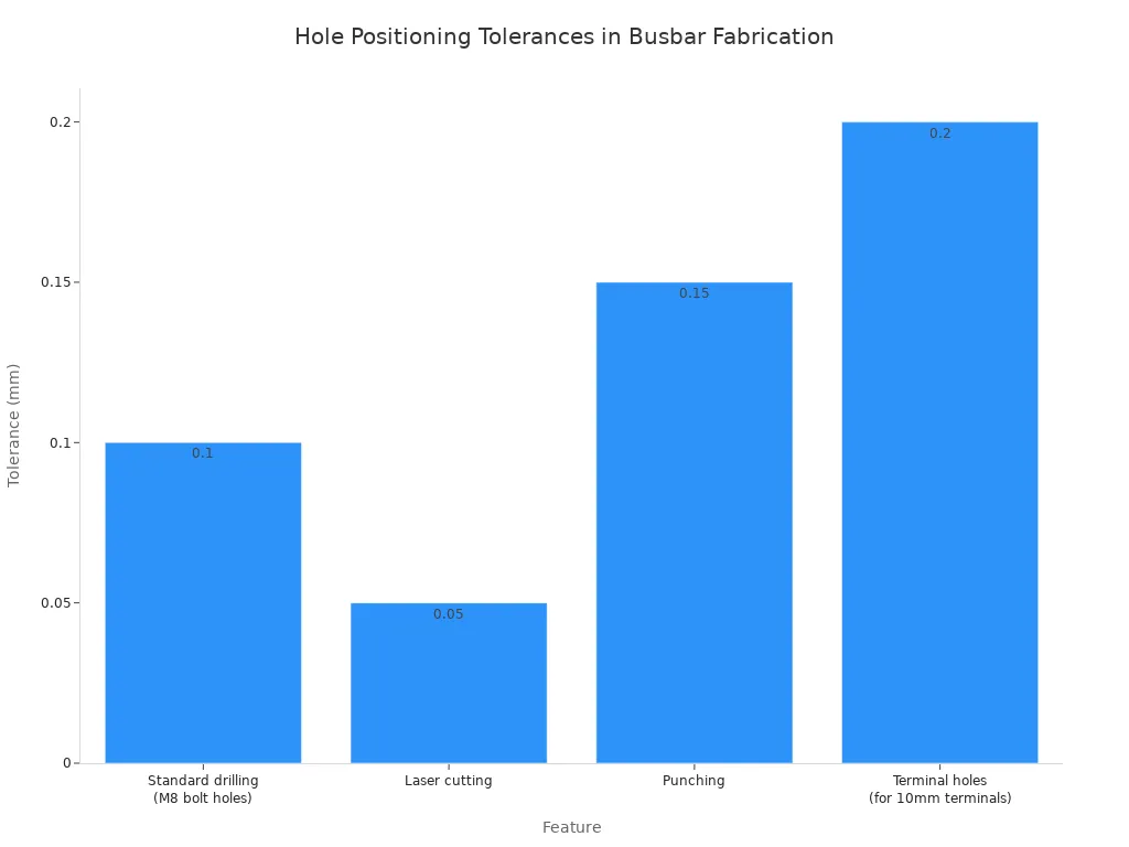
You should use positional tolerance frames for critical cell connection holes. Datum A sets the module plane, Datum B lines up with the cell stack direction, and Datum C references end features. This creates cylindrical tolerance zones that stop square accumulation errors. Precise fixturing and CNC punching keep hole positions within these limits every time.
Optical measurement systems beat manual inspection by a wide margin. These non-contact systems reach accuracy of 0.035mm, checking directly against CAD nominal data. Unlike coordinate measuring machines that need skilled technicians and fixtures, optical systems let an operator place the part and press a button. They give immediate variable data and automatic correction feedback, removing alignment errors common with contact probing methods.
Real-time quality control catches defects before they turn into expensive failures. Modern detection systems monitor visible light, infrared, and laser reflection signals across a wide wavelength range from 220 to 1800 nm. High-frequency sampling at 10 kHz spots issues like incomplete penetration and porosity before they harm the final product.
As factories adopt Industry 4.0 principles, busbar processing machines are integrated into digital workflows. They communicate with ERP and MES systems, enabling real-time tracking and quality control.
Suzhou Kiande's Busduct Production Line shows this integration in action. Barcode scanning links each busbar to its production data, giving full traceability. The system automatically adjusts machine parameters based on the recognized busbar type. Work orders and data move automatically between the ERP and the production line, removing manual data entry errors. This end-to-end digitization provides real-time quality results, allowing immediate corrective action. You gain complete tracking and audit readiness while cutting weld variability substantially compared to open-loop systems. These precision solutions turn quality control and management from a reactive checkpoint into a proactive, data-driven process that protects your reputation and your bottom line.
Tooling failures disrupt your production flow and compromise part quality. Worn tools create burrs and dimensional drift that force rework. Die misalignment produces inconsistent parts that fail inspection. Understanding these equipment challenges helps you implement effective solutions before they impact your output.
Tool wear directly affects your finished product. Dull blades tear copper instead of shearing it cleanly, leaving rough edges that require secondary deburring operations. Dimensional accuracy suffers as cutting edges degrade, pushing measurements outside acceptable tolerances. You need a proactive maintenance strategy to prevent these busbar manufacturing problems.
Carbide tooling outperforms high-speed steel in demanding production environments. Carbide tools measure 90–94 on the Rockwell hardness scale, while HSS tools reach only 62–64. This hardness advantage translates into practical benefits: carbide taps last 5 to 20 times longer than HSS taps in high-temperature applications. Carbide also operates 4 to 12 times faster than HSS under identical conditions, reducing cycle time significantly. The higher initial investment pays off through fewer interruptions and consistent quality during mass production.
A structured maintenance schedule protects your tooling investment. Follow this framework to keep equipment performing at peak levels:
Maintenance Frequency | Recommended Actions |
|---|---|
Daily | Clean cutting surfaces of copper and aluminum swarf; confirm tooling seats correctly |
Weekly | Lubricate guide rails to OEM specifications; check alignment reference points |
Monthly | Measure die clearance against new-tool baseline; calibrate alignment |
Annual | Replace dies and blades as matched pairs; perform full machine re-calibration |
On Condition | Replace blades immediately upon visible edge rounding or chipping |
Never run worn blades. Replace upper and lower blades together as a matched set to maintain proper cutting geometry.
Die misalignment creates subtle but damaging inconsistencies across your production run. Misaligned holes appear in slightly different positions on each part, causing assembly failures and field problems. These errors waste expensive copper and erode customer confidence in your fabrication capabilities.
Routine alignment checks prevent these issues. Measure die clearance against your baseline readings monthly and verify alignment reference points weekly. Precision-ground dies maintain tighter tolerances than standard tooling, reducing variation across long production runs. When you detect drift, recalibrate immediately rather than waiting for visible defects.
Advanced busbar machines minimize alignment challenges through stable processing. Suzhou Kiande's Busbar Machine uses rigid construction and precise guides that hold alignment through continuous operation. This stability reduces the frequency of adjustments you need to make, letting you focus on production rather than troubleshooting. The bending process also benefits from consistent tool positioning, producing accurate angles part after part.
Investing in quality tooling and following disciplined maintenance schedules reduces scrap, prevents overheating from poor connections, and delivers reliable results. These solutions address the root causes of equipment-related defects, improving your overall process efficiency and product quality.
How you handle and store busbar materials directly affects the quality of the final product. Two common problems—surface oxidation and material warping—create hidden defects that only show up after assembly. Fixing these issues early prevents costly rework and ensures reliable connections.
Surface oxidation on copper creates a tricky challenge. The oxide layer is only 0.1 to 5 μm thick. Pure copper resistivity is 1.68 × 10⁻⁶ Ω·cm, while copper oxide resistivity reaches roughly 10⁴ to 10⁶ Ω·cm—a million times higher. However, for a 100 mm × 10 mm × 2 mm busbar, the bulk resistance is only about 0.085 mΩ. Adding a 5 μm oxide layer increases this by only 0.003 mΩ. This tiny change means surface oxidation does not change the conductor's natural ability to carry electricity.
The real problem happens at the contact interface. When two oxidized copper surfaces meet, only a few high spots actually touch. The oxide layer forces current through these limited points. Contact resistance can jump by a thousandfold. High current flowing through this high-resistance contact creates concentrated heat. This heat speeds up more oxidation, creating a loop that can eventually burn out the connection. Surface oxidation seriously harms joint performance and leads to electrical connection issues. You prevent this by storing materials in controlled environments, cleaning surfaces before assembly, and applying protective coatings that stop oxidation from forming.
Warping in busbars comes from internal stresses or improper handling. Material flatness matters because any deviation affects how the busbar sits against other parts. Poor contact surfaces lead to reduced reliability. You must fix flatness before moving forward with any fabrication step.
The solution starts with proper storage. Store copper bars flat on level racks to prevent sagging. Avoid stacking heavy loads on top of stored materials. For materials that arrive with existing warping, use straightening equipment before processing. Precision rollers apply controlled pressure to restore flatness without damaging the surface. Adding these steps to your process removes warping errors before they affect your final product. Keeping materials flat throughout the copper busbar manufacturing process ensures consistent quality. These solutions prevent common fabrication problems and protect your production efficiency.
Heat generation during cutting and punching creates hidden defects that compromise your final product. When tools generate excessive friction, the copper surface hardens locally. This work-hardening effect makes subsequent bending operations risky. The material becomes brittle in those zones, increasing the likelihood of cracking precisely where you need clean, reliable bends. You might not see the damage immediately, but it appears later as failed parts and wasted material.
The root cause of heat-related damage is friction between the tool and the workpiece. High cutting speeds generate more heat than the material can dissipate. This concentrated thermal energy alters the copper's microstructure, creating hard spots that resist further forming. You also risk micro-cracks along the cut edge that propagate during bending.
Your first solution is proper lubrication. A consistent coolant flow removes heat from the cutting zone and extends tool life simultaneously. For copper, use water-soluble coolants that provide both lubrication and cooling without leaving residues that affect conductivity. Apply coolant directly to the cutting interface, not just to the general area.
Optimizing cutting speeds also controls heat buildup. Slower speeds generate less friction but reduce throughput. You need to find the balance point for your specific material thickness and temper. Thicker copper bars require slower speeds because the larger contact area generates more heat. Thinner materials can handle faster processing without reaching dangerous temperatures.
Tool selection matters equally. Sharp tools cut cleanly with minimal friction. Dull tools rub against the material, generating excessive heat before they finally shear. High-speed steel tools work for low-volume production, but carbide tooling maintains its edge longer under continuous operation. The sharper the cutting edge, the less heat you generate and the cleaner the cut you achieve.
A simple rule guides your process: if the cut edge shows discoloration or the tool feels hot to the touch immediately after operation, you are generating too much heat. Adjust your speed, increase coolant flow, or replace the tooling before continuing production.
Manual operations introduce variability that no amount of operator skill can eliminate. Each worker bends slightly differently, positions parts marginally off-center, and applies inconsistent pressure. These small variations accumulate into measurable differences across your production run. Automation removes this human factor, delivering identical results for every part.
Fully automated busbar production lines address the most persistent busbar manufacturing problems at their source. Suzhou Kiande's automatic busbar assembly line demonstrates how complete automation transforms your fabrication process:
Automatic positioning, conveyance, and riveting ensure every product meets consistent assembly standards
Elimination of human error reduces material waste substantially
High precision and stable output minimize downtime during production
Compatibility with both rivet and bolt fixing methods in a single machine
Support for two-piece and four-piece busduct housing structures
The system handles busduct lengths up to 6000mm with a working efficiency of approximately 3000mm per 2 minutes. Its network control system enables online maintenance when you need it. The 380–415VAC, 50–60Hz power supply with 20kW capacity integrates easily into standard industrial facilities.
"Fully automated, modular production equipment enables factories to achieve stable output, uniform product quality and traceable manufacturing processes."
Kiande's integrated busduct production line series provides a complete solution for consistent quality. You can customize the automatic assembly line for different busbar specifications, whether two-piece or four-piece configurations. The barcode recognition system automatically identifies product types and adjusts operating parameters without manual intervention. This ensures uniformity across every part you produce.
The line integrates PLC, touch screen, and industrial control systems for seamless data linkage with ERP systems. This integration lays the foundation for a digital smart factory where you track every aspect of production in real time. From raw material processing through inspection and packaging, the system minimizes human intervention. This end-to-end automation maintains stable quality even during high-volume mass production runs.
Automation also addresses overheating concerns indirectly. Consistent pressure and positioning during assembly prevent uneven contact between busbar joints. Poor contact creates high-resistance points that generate excessive heat during operation. By ensuring every joint assembles identically, you prevent these hot spots before they develop. This proactive approach to quality control and management protects both your products and your reputation.
The bending process benefits particularly from automation. CNC-controlled machines apply precise force at exact positions every time. You eliminate the trial-and-error approach common in manual bending. Each bend matches the previous one within tight tolerances, producing copper components that fit together perfectly during installation.
Automation transforms quality control from an inspection activity into a prevention strategy. Instead of catching defects after production, you prevent them through consistent process execution. This shift reduces scrap rates, lowers rework costs, and delivers reliable products to your customers. The investment in automated equipment pays for itself through reduced waste and increased throughput.
These solutions address the core challenges of busbar manufacturing problems through systematic process control. By managing heat generation and embracing automation, you achieve the consistency that modern electrical systems demand. Your fabrication operation becomes more efficient, your products more reliable, and your competitive position stronger in an increasingly demanding market.
Most busbar manufacturing problems share common roots in tooling, material, or process parameters. You cannot fix them in isolation. Proactive root cause analysis and preventive maintenance outperform reactive troubleshooting every time. You save money and reduce downtime when you address issues before they escalate.
Investing in precision equipment transforms your operation. Suzhou Kiande's Busbar Machine and Busduct Production Line deliver consistent results. Pair this technology with operator training for maximum benefit. Your team must understand how to leverage these tools effectively.
Mastering these solutions elevates product quality and reduces waste. You gain a competitive edge in the electrical manufacturing industry. Every copper connection you produce meets exacting standards. Your fabrication process becomes more reliable, your copper usage more efficient, and your reputation stronger.
Pick low-oxygen grades like C10100 or C10200 for tough bending jobs. These oxygen-free coppers have fewer impurities that create weak spots between grain boundaries. Higher purity means the metal bends better and resists cracking. For aluminum parts that need more strength, use EN-AW 6101 alloy instead of EN-AW 1050A.
Follow a regular maintenance plan instead of waiting for visible damage. Check cutting edges every day for rounding or chipping. Compare die clearance to your starting measurements each month. Swap out blades right away when you see wear. Replace dies and blades together as matched pairs once a year to keep cutting geometry correct and stop burrs from forming.
The CNC system stores springback data for different materials and thicknesses. Before each bend, it figures out a correction angle using your busbar's width and material type. After the first bend, sensors measure the real angle. The machine then does a second bend to fix any leftover error, hitting accuracy within ±0.3 degrees.
Automated lines pay off most when you run steady, high-volume production. If manual work causes uneven quality over long runs, automation removes that inconsistency. The system cuts labor costs, reduces material waste, and connects with ERP systems for tracking. Add up your current scrap and rework expenses to find your break-even point.

