
Views: 0 Author: Site Editor Publish Time: 2026-08-04 Origin: Site


In high-volume switchgear, control panel, and power distribution manufacturing, the primary bottleneck is rarely the execution speed of a single cut or bend; it is the transition time between different fabrication tasks. Moving heavy copper or aluminum busbars between isolated, single-purpose stations introduces material handling delays, increases the risk of dimensional inaccuracies, and inflates labor costs. Traditional setups suffer from high downtime during tooling changeovers and manual measuring.
Modern integrated systems consolidate shearing, punching, and bending into a unified footprint. These range from a compact 3 in 1 busbar machine to a fully automated busbar joint processing center. Understanding exactly how a modern Busbar Machine mechanically and digitally switches between these tasks is critical for evaluating production throughput, equipment ROI, and operational scalability.
Station Independence: High-end units utilize independent hydraulic cylinders and dedicated motor-pump groups, allowing simultaneous multi-tasking without pressure drops or station interference.
Tooling Architecture: The shift from manual single-die swapping to integrated rotary turret systems in a digital busbar punching machine drastically reduces mechanical changeover times from minutes to seconds.
Digital Orchestration: CNC and PLC integration allows operators to program complex, multi-step workflows (e.g., punch-then-bend) via a single interface, minimizing manual material repositioning.
Risk vs. Reward: While consolidated systems save floor space and handling time, they introduce single-point-of-failure risks and thermal load challenges that require stringent preventative maintenance protocols.
Defining the unified footprint requires looking at how cutting, punching, and bending stations are integrated into a single chassis. The primary goal is to minimize material travel distance and operator handling. In a standard fabrication shop, moving a 3-meter, 10mm thick copper bar from a standalone shear to a standalone punch press requires carts, hoists, and multiple operators. A multifunction busbar processing machine eliminates this transit. The operator loads the raw stock once, slides it laterally between the adjacent stations, and completes all operations within a two-meter working radius. This physical consolidation directly reduces cycle times and lowers the physical strain on the workforce.
The internal hydraulic architecture dictates how the machine handles multiple tasks. Sequential systems, often found in entry-level equipment, rely on a single hydraulic pump. Directional solenoid valves divert fluid power to one station at a time. If an operator is punching a hole, the bending and shearing stations are temporarily locked out. This lowers the initial capital cost and reduces the complexity of the hydraulic manifold. However, it severely limits operations in a busy shop, as only one task can occur at any given moment.
Simultaneous processing configurations utilize multi-pump, multi-motor setups. These systems feature dedicated hydraulic circuits for each station. Up to three operators can work independently at the punching, shearing, and bending stations without experiencing hydraulic lag or pressure drops. If operator A is shearing a 12mm bar, operator B can simultaneously bend a 10mm bar without the machine stalling. This multi-cylinder approach requires larger fluid reservoirs and more robust motor groups, but it effectively triples the throughput capacity of the footprint.
The physical arrangement of the stations on the machine deck impacts material flow. A linear layout places the shear, punch, and bender in a straight line. This works best for long, continuous material feeds, allowing raw copper bars to move straight through the machine along a roller conveyor. However, it requires significant floor space on both ends for material support, and operators must walk the length of the machine to switch tasks.
A triangular or radial layout creates a space-saving footprint. It clusters the three stations around a central hub, minimizing operator movement. The worker simply pivots to access the next station. This design requires careful workspace clearance planning. When bending long busbars, the sweeping arc of the material can easily collide with adjacent equipment or walls if the machine is placed too close to a corner.
Measure the maximum length of raw copper or aluminum stock you process daily.
Calculate the swing radius required for a 90-degree bend on your longest typical part.
Map the floor space to ensure at least one meter of clearance beyond the maximum swing radius.
Position the machine near the raw material racks to minimize forklift travel.
Ensure overhead lighting does not cast shadows on the punching and shearing alignment guides.
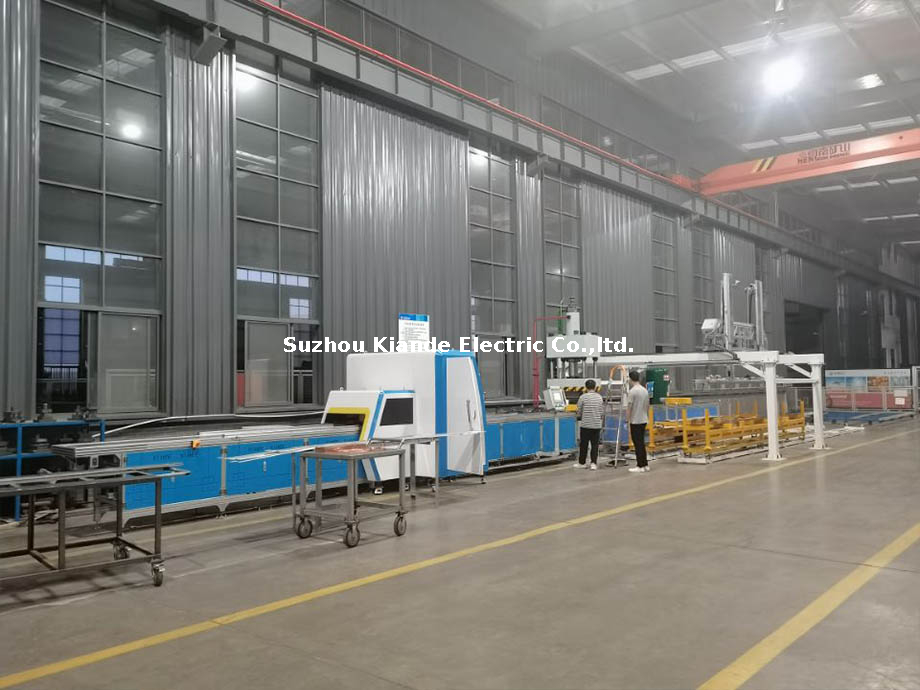
High-capacity, fully enclosed automated lines scale up these individual stations into a continuous production system. They incorporate automated material loading magazines, servo-driven positioning conveyors, and robotic handling arms. This evolution removes manual feeding entirely. The system pulls raw stock from a rack, feeds it through the punching and shearing modules based on CNC coordinates, and ejects finished parts onto a sorting table. This level of automation is necessary for facilities producing thousands of identical switchgear components per week.
Switching between tasks requires physical changes to the machine's contact points. The speed, accuracy, and safety of these tooling changes define the machine's overall mechanical efficiency. Every minute spent wrestling with a stuck die is a minute of lost production.
Traditional single-die swapping requires operators to manually unbolt a punch, remove the die from the lower block, insert new tooling, and carefully align the clearances. This process takes several minutes and introduces the risk of alignment errors. If the punch and die are misaligned by even a fraction of a millimeter, the tool will crash, shattering the hardened steel and potentially injuring the operator.
A multi-station rotary turret holds multiple punch-and-die sets simultaneously. Found on a high-end digital busbar punching machine, these turrets typically hold 4, 6, or 8 tool sets. Automated turret indexing aligns the correct punch with the hydraulic ram in under two seconds. The operator selects the required hole size on the touchscreen, and the turret rotates into position. This eliminates manual alignment errors, reduces operator fatigue, and prevents tooling components from getting lost on the shop floor.
| Tooling System | Average Changeover Time | Alignment Risk | Operator Effort |
|---|---|---|---|
| Manual Single-Die | 3 to 5 Minutes | High (Manual Calibration) | High (Requires Wrenches) |
| Manual Turret | 10 to 15 Seconds | Low (Pre-aligned) | Medium (Manual Rotation) |
| CNC Auto-Index Turret | Under 2 Seconds | Zero (Factory Calibrated) | None (Screen Input) |
The bending station must accommodate flat bending, vertical bending (edge bending), U-bending, and cable lug pressing. Switching between these modes requires swapping heavy modular die blocks. Modern machines utilize quick-release pin systems. Operators pull a locking pin, lift out the V-die, and drop in a U-bending block without using any hand tools. This modularity keeps the workflow moving.
Material springback complicates bending transitions. Pure C11000 copper behaves differently than 6101 structural aluminum alloys. When bent to 90 degrees, aluminum will spring back further than copper once the hydraulic pressure is released. The bending station mechanically or digitally adjusts the stroke depth when switching materials to compensate for this physical property. Advanced systems use automated tool recognition sensors to verify the correct die is installed before allowing the press to actuate, preventing material damage.
Fixed-blade setups often struggle with varying material dimensions, leaving burrs on thinner stock and struggling to penetrate thicker bars. Adjustable double-cut shearing dies eliminate scrap and deformation. They punch out a small slug of material, providing a clean, flat edge on both sides of the cut without the typical V-shaped distortion seen in single-blade guillotine shears.
Machines manage the transition from cutting thin, wide busbars (e.g., 3mm x 120mm) to thick, narrow bars (e.g., 12mm x 40mm) through rigid blade guides and heavy-duty shear housings. High-quality systems maintain strict tolerances to prevent burr formation, meaning operators do not need to manually adjust blade clearances when switching between different copper thicknesses. This "load and cut" capability is vital for maintaining high throughput.
Mechanical speed means little without intelligent control. Digital integration transforms isolated mechanical tasks into a cohesive, predictable production sequence. The control system acts as the brain, coordinating the hydraulic muscle.
Touchscreen PLCs and industrial PCs replace manual limit switches, physical measuring stops, and hand-marked templates. Operators no longer use tape measures and scribes to mark hole locations. They input core parameters such as material thickness, width, and copper grade directly into the interface.
The system uses these inputs to automatically calculate stroke depth and punch positioning. It eliminates trial-and-error scrap. The interface stores hundreds of part programs, allowing instant recall of previous jobs. When an order for a specific grounding bar comes in, the operator selects the file, and the machine automatically sets the bending angles and punch coordinates.
CAD/CAM software integration allows engineers to import 2D and 3D busbar designs directly into the machine's control unit. DXF and STEP files transfer exact hole coordinates and bend angles without manual data entry. This bridge between the engineering office and the shop floor eliminates transcription errors.
Automated sequencing algorithms dictate the order of operations. The software determines the most efficient path through the machine. It typically punches all holes first while the bar is long and easy to clamp, shears the part to length, and performs the bends last. This sequence minimizes tool changes, optimizes material yield, and prevents operators from bending a part before punching a hole that would be inaccessible after the bend.
Servo-driven X and Y axes automatically move, clamp, and position the busbar for the next task. The operator simply loads the raw bar into the pneumatic clamps and presses start. The servos pull the material to the exact coordinates required for each punch, moving with sub-millimeter accuracy.
The digital system maintains a single, unified datum point across different tasks. This prevents the compounding of dimensional tolerances. When transitioning from punching to bending, the software references the same origin point. If a hole is punched 50mm from the edge, and a bend is required 100mm from the edge, the system calculates both from the exact same zero point, ensuring the final assembly aligns perfectly in the switchgear cabinet.
Evaluating equipment requires looking beyond maximum tonnage and raw motor horsepower. The true metric of performance is how quickly the machine transitions from one profitable task to the next. Idle time during setup is the enemy of manufacturing efficiency.
Applying Single-Minute Exchange of Die (SMED) concepts helps calculate the true return on investment. Auditing the time spent locating tools, adjusting backstops, and running test pieces reveals hidden costs. If an operator spends ten minutes setting up a bend, and only two minutes executing the bends for a batch of five parts, the process is highly inefficient.
| Fabrication Task | Traditional Setup Time | CNC Automated Setup Time | Primary Time Saving Mechanism |
|---|---|---|---|
| Punch Coordinate Setup | 4 to 6 Minutes | 5 Seconds | Servo-driven X/Y axis positioning |
| Bend Angle Calibration | 5 to 10 Minutes | 10 Seconds | Digital springback compensation |
| Shear Length Measurement | 2 to 3 Minutes | 2 Seconds | Automated CNC backgauge |
Switching from high-tonnage tasks like punching 15mm thick copper to high-precision tasks like micro-angle bending tests the machine frame. The mechanical stability, rigidity, and deflection limits of the chassis determine if tolerances drift over time. A weak frame will flex during heavy shearing. This flexing can throw off the calibration for subsequent bending operations, resulting in parts that do not fit into the final assembly.
Safety interlocks, light curtains, and dual-hand control switches prevent accidental actuation. When an operator switches from the punching station to the bending station, the system must recognize the change in location and disable the unused stations to prevent accidents.
Physical guarding designs balance maximum operator access for fast tooling setup with absolute safety during operation. Clear sightlines and ergonomic working heights reduce fatigue during complex, multi-step fabrications. If an operator has to bend over awkwardly to see the shear blade alignment, mistakes will happen, and safety is compromised.
Consolidating multiple processes into one machine introduces specific operational vulnerabilities. Identifying these risks early ensures continuous production and protects the equipment investment.
If the central hydraulic unit, PLC controller, or main power distribution system fails, all processing capabilities halt. A single breakdown stops cutting, punching, and bending simultaneously, effectively shutting down the entire busbar fabrication line.
Mitigate this by implementing modular PLC architectures and redundant hydraulic backup pumps. Ensure robust service-level agreements with suppliers for immediate parts availability and technical support. Keep critical spare parts, such as solenoid valves and contactors, in stock on the shop floor.
Extreme heat generation occurs when switching rapidly between high-demand tasks in multi-user setups. Pressure drops can happen if three operators actuate heavy cylinders at the exact same moment, causing the bending ram to stall mid-stroke.
Size the hydraulic reservoir correctly to allow adequate fluid cooling time. Integrate automated oil chillers or air coolers to maintain optimal fluid viscosity during continuous three-shift operations. Use proportional valves to regulate pressure dynamically across all stations, ensuring smooth, consistent force delivery.
Undetected tool wear in one station leads to defects in subsequent steps. A dull punching die creates heavy burrs on the bottom of the copper bar. These burrs can cause micro-cracking when the copper is stretched over a V-die during the bending phase.
Implement digital stroke-counting systems and tonnage monitoring to track tool life. Perform routine physical inspections of blade clearances and punch sharpness to catch wear before it damages the material. Replace punches and dies as matched sets to maintain proper clearance.
Transitioning manual operators to advanced CNC interfaces can result in programming errors, crashed tooling, or scrap material. The digital workflow requires different skills than manual layout and physical measuring.
Choose machines with intuitive Human-Machine Interfaces that use visual icons rather than complex text menus. Utilize 3D simulation features to visualize the bending sequence on the screen before physical execution, allowing operators to catch collision errors early. Invest in structured vendor training programs to build operator confidence in the digital systems.
The overall efficiency of a fabrication setup is dictated by the speed, repeatability, and digital integration of its task-switching mechanisms. Maximum hydraulic tonnage is only one factor. The ability to move seamlessly from cutting to punching to bending determines actual daily output and profitability.
Low-to-medium volume workshops should prioritize systems with quick-change manual tooling, sequential hydraulic systems, and simple digital angle controls. High-volume industrial production mandates dedicated units with multi-station rotary turrets, simultaneous hydraulic operation, and direct CAD/CAM software integration.
Perform a time-and-motion study of your current changeover processes to identify exact bottleneck durations.
Calculate the cost of material handling delays and scrap generated between disconnected stations.
Request cycle-time demonstrations from vendors using your most complex busbar schematics.
Audit your facility's floor space to determine the optimal layout configuration for a new machine.
A: Yes, provided the machine is equipped with a multi-pump hydraulic system. This configuration ensures independent pressure to each station, preventing lag or sudden drops in force when multiple cylinders actuate simultaneously.
A: A manual die change typically takes 3 to 5 minutes per hole size. A digital machine equipped with an automated rotary turret indexes to a new punch size in under two seconds.
A: It depends on the model. Sequential machines use one pump and directional valves, allowing only one operation at a time. Simultaneous machines use multiple pumps to allow independent, concurrent operations.
A: The operator inputs the material type and thickness into the interface. The software references an internal database of material properties and automatically adjusts the over-bend angle and stroke depth to achieve the target dimension.
A: High-quality double-cut shearing stations can typically process copper and aluminum busbars up to 12mm or 16mm thick without manual blade clearance adjustments, relying on rigid guides to prevent burrs.
A: Connecting to a larger automated center requires CAD/CAM compatibility, typically accepting DXF or STEP files. It also requires network connectivity to synchronize material feed rates and coordinate robotic handling.

