
Views: 0 Author: Site Editor Publish Time: 2026-08-02 Origin: Site


Poor busbar cutting surface quality carries hidden operational costs that manifest long after the assembly process is complete. Micro-burrs, uneven shear planes, and material deformation directly increase contact resistance at joint interfaces. This elevated resistance leads to localized heating, thermal runaway, and ultimately, catastrophic switchgear failure. Achieving a perfectly flat, burr-free cut relies entirely on the mechanical precision and structural integrity of the equipment used, rather than the manual skill of the operator.
Scaling production while maintaining strict dimensional tolerances presents a significant challenge for panel builders and switchgear manufacturers. When evaluating equipment, buyers must look past basic capacity specifications like maximum material thickness. Selecting the right Busbar Machine requires a detailed assessment of the specific mechanical, hydraulic, and tooling factors that dictate shear quality and long-term reliability on the shop floor.
Shear Mechanism Design Dictates Deformation: Double-column shear structures significantly reduce material waste and edge deformation compared to traditional single-shear designs.
Blade Clearance is the Primary Quality Variable: Incorrect clearance relative to busbar thickness is the leading cause of burrs, slanted cuts, and accelerated tool wear.
Machine Rigidity Prevents Deflection: High-tonnage hydraulic systems must be paired with heavy-duty, stress-relieved frames to maintain blade alignment during the cutting cycle.
Application Dictates Equipment Type: High-volume, high-precision requirements may necessitate a dedicated joint bar cutting center, while varied, lower-volume production favors a multifunction setup.
In industrial applications, an acceptable cut must meet strict criteria for perpendicularity tolerances, maximum allowable burr height, and surface roughness. These metrics directly influence both electrical performance and mechanical assembly during copper busbar fabrication. A cut that deviates from these tolerances introduces immediate risks to the electrical system's integrity.
The physics of joint interfaces dictate that uneven cutting surfaces reduce the effective contact area between joined busbars. When two surfaces do not mate perfectly, current is forced through a smaller cross-sectional area, increasing micro-ohm resistance. This poor surface finish correlates directly with thermal runaway in high-amperage applications, degrading system efficiency and safety over time. Engineers must account for the fact that even a fraction of a millimeter of deviation can cause a massive spike in operating temperature under full load.
To understand the severity of this issue, consider the thermal dynamics of a 4000A switchgear system. A joint with a rough surface finish might only achieve 60% physical contact area. The remaining 40% consists of microscopic air gaps, which act as insulators. The current crowding through the actual contact points generates excessive heat, which accelerates the oxidation of the copper. This oxidation further increases resistance, creating a destructive feedback loop that inevitably leads to joint failure.
Non-perpendicular cuts create slanted edges that complicate the assembly of complex busbar routing. Misaligned joints require forced fitting, which introduces mechanical stress into the system. Over time, thermal cycling and electromagnetic forces during short-circuit events will exploit these built-in stresses, potentially causing the bolted connections to loosen.
Furthermore, sharp burrs left on the cut edge risk piercing heat-shrink tubing or epoxy insulation. This compromised insulation can lead to dielectric breakdown and dangerous short circuits within the enclosure. Panel builders spend significant time applying insulation, and a single burr can negate that entire effort, requiring complete disassembly and rework.
| Defect Type | Root Cause | System Impact |
|---|---|---|
| Micro-Burrs | Dull blades or improper clearance | Insulation puncture, short circuits |
| Slanted Cut | Frame deflection or poor clamping | Misaligned joints, mechanical stress |
| Edge Rollover | Excessive blade clearance | Reduced contact area, thermal runaway |
| Galling | Lack of lubrication | Rough surface finish, accelerated tool wear |
Buyers must assess specific engineering features when reviewing machine specifications. The mechanical architecture of the equipment determines its ability to produce clean, repeatable cuts across thousands of operational cycles.
Single-blade shearing mechanisms often leave a slight bevel on the cut edge and generate material scrap. The blade acts like a scissor, pushing the material down before shearing it, which inherently causes some degree of deformation. In contrast, double-blade or punch-shear mechanisms produce a flat, scrap-free cut by shearing the material evenly from both sides simultaneously.
The shear angle also plays a major role in the cutting process. An optimized angle reduces the required cutting force and results in a smoother edge finish. Machines with adjustable shear angles allow operators to fine-tune the cutting dynamics based on the specific thickness and temper of the copper or aluminum being processed.
Blade profiles significantly affect stress concentration during initial material penetration. Flat blades can cause material displacement, pushing the copper outward and creating a wider profile at the cut line. Arc-shaped or V-cut blades minimize this lateral movement by piercing the center of the material first and shearing outward.
This specialized geometry prevents edge rollover, particularly when processing soft copper alloys. By controlling the direction of material displacement, V-cut blades ensure a square and clean cut that requires zero secondary deburring or grinding.
The metallurgical composition of the cutting blades dictates their lifespan and performance. Common blade alloys include Cr12MoV, D2/SKD11, DC53, and H13. These materials are typically heat-treated to achieve a Rockwell Hardness (HRC) rating of 58–62. High hardness ratings ensure the blade maintains its sharp edge over thousands of cycles without chipping or deforming.
When blade edges degrade, the machine begins to tear the material rather than shearing it cleanly. This tearing action results in severe burrs and rough surfaces. Regular inspection of the blade edges is necessary to catch this degradation before it impacts production quality.
Machine rigidity is essential to prevent blade deflection under high-tonnage loads. A stress-relieved, heavy-duty frame maintains parallel blade alignment throughout the cutting cycle. If the frame flexes even a fraction of a millimeter during operation, the blades will misalign, causing slanted cuts and rapid tooling wear.
The hydraulic cylinder must deliver consistent, linear force. Any pulsation or pressure drops during the shear stroke will cause the blade to stutter, leaving visible chatter marks on the cut surface. High-quality hydraulic systems use proportional valves to ensure smooth power delivery from the moment the blade contacts the material until the cut is complete.
Operators must manage specific variables that the machine must be capable of accommodating to ensure consistent cut quality. Even the most rigid machine will produce poor cuts if the operational parameters are set incorrectly.
Blade clearance is the physical gap between the upper and lower blades as they pass each other. This gap is typically set at 5-10% of the material thickness. Proper adjustment is the single most important operational variable for achieving clean cuts.
Measure the exact thickness of the busbar using digital calipers.
Calculate 5% to 8% of that thickness for standard copper alloys.
Adjust the lower blade position using the machine's clearance adjustment mechanism.
Use feeler gauges to verify the gap is uniform across the entire length of the blade.
Perform a test cut and inspect the edge for burrs or rollover.
Excessive clearance causes material rollover and heavy burrs because the material is bent into the gap before it shears. Insufficient clearance leads to secondary shearing, where the blade cuts the material twice, leaving a jagged edge and causing rapid tool wear.
The shearing behavior of T2/C11000 copper differs significantly from electrical-grade aluminum. Copper possesses higher tensile strength and ductility, meaning it requires more force to shear but is less prone to cracking. Aluminum is softer but more abrasive, which can lead to material sticking to the blade.
The machine's hydraulic delivery and blade setup must adjust for these differing properties. When cutting aluminum, operators often need to reduce the blade clearance slightly to account for the material's lower shear strength and prevent it from extruding into the blade gap.
Cutting fluid or tool-surface lubrication reduces friction and heat generation during the shear stroke. Proper lubrication prevents material pick-up, known as galling, on the blade face. Galling occurs when microscopic particles of copper or aluminum weld themselves to the steel blade due to extreme pressure and friction.
Once galling starts, it rapidly degrades the surface finish of subsequent cuts. Applying a light coat of specialized cutting oil or using blades with anti-friction coatings directly improves the surface finish of the sheared edge and extends tooling life.
Specific machine components, particularly the clamping system, are vital for preventing cutting defects in a joint bar cutting center. If the material moves during the cut, the resulting edge will be compromised.
Robust, automated hold-down clamps are necessary during the shearing process. As the blade contacts the material, it exerts a massive downward and lateral force. Inadequate clamping allows the busbar to tilt or shift during the cut. This movement results in out-of-square edges, dimensional inaccuracies, and potential damage to the tooling.
High-quality machines utilize multiple clamping points positioned as close to the shear line as possible. This proximity prevents the material from bowing upward as the blade pushes through, ensuring a perfectly perpendicular cut.
Steel clamps offer maximum rigidity and clamping force, but they carry the risk of marring the material surface, especially on softer aluminum busbars. Urethane-faced clamps protect the surface finish by providing a non-marring contact point. However, urethane pads compress slightly under load and require periodic replacement due to wear.
The choice depends on the specific finish requirements of the application. For bare copper that will be hidden inside an enclosure, steel clamps are usually preferred for their durability. For plated or highly polished busbars, urethane clamps are necessary to prevent cosmetic damage.
Dynamic hydraulic clamping provides self-adjusting pressure that adapts to material thickness, ensuring consistent hold-down force regardless of operator input. The hydraulic system automatically applies the correct pressure before the shear stroke begins.
Manual clamping setups are prone to human error. If an operator fails to tighten the clamp sufficiently, the material will shift. If they overtighten it, they can deform the busbar before the cut even starts. Hydraulic clamping eliminates this variability.
Choosing the right machine architecture depends on operational context, production volume, and setup flexibility requirements. Shop managers must evaluate their specific workflow to determine which system provides the best return.
A dedicated CNC busbar cutting machine offers significant throughput advantages. These systems feature automated feeding, continuous shearing, and integrated sorting conveyors. They are designed to process thousands of identical parts with minimal operator intervention.
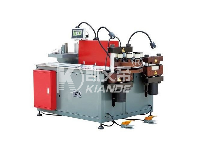
Conversely, a multifunction busbar cutting station provides versatility. These units allow operators to punch, bend, and cut within a single footprint. While they cannot match the raw speed of a dedicated cutting line, they are ideal for custom panel builders who process small batches of highly varied parts.
Evaluating Capital Expenditure (CapEx) requires balancing the initial investment against long-term operational savings. A high-end machine with automated features requires a larger upfront investment but drastically reduces labor costs and material waste.
Reduced scrap and the elimination of rework processes like grinding and deburring significantly improve Return on Investment (ROI) over the machine's lifecycle. When calculating ROI, factor in the hourly cost of an operator standing at a bench grinder deburring poorly cut busbars. A machine that produces a clean cut straight off the blade pays for itself rapidly by eliminating this secondary operation.
Maintaining cut quality post-purchase requires strict adherence to quality control and preventative maintenance protocols. Even the best equipment will degrade if ignored.
Practical methods for verifying cut quality must be implemented on the production floor. Operators should not rely on visual inspection alone. Using go/no-go gauges for squareness ensures the cut is perpendicular. Dial indicators can measure edge straightness, while tactile surface roughness testers quantify the smoothness of the shear plane.
Implementing a first-article inspection routine ensures the machine is set up correctly before a large batch is run. If the first piece fails the quality check, the operator must adjust the blade clearance or clamping pressure before proceeding.
A realistic maintenance schedule is non-negotiable. Routine tasks include checking hydraulic fluid levels and looking for leaks around the cylinder seals. Guide rails must be lubricated weekly to prevent binding and ensure smooth blade travel.
Blade rotation or sharpening intervals must be tracked based on cycle counts, not just elapsed time. Neglecting these tasks leads to degraded cut quality, increased stress on the hydraulic system, and potential catastrophic machine failure.
Double-cut shearing mechanisms generate fine copper slivers as they punch out the small section of material between the blades. Automated extraction systems or gravity-fed chip chutes are necessary to manage this waste.
If these slivers are not removed, they can accumulate in the blade guides or under the clamping mechanisms. This contamination causes mechanical binding, throws off dimensional accuracy, and can severely damage the tooling.
Standard operating procedures (SOPs) must dictate the verification of blade clearance and the inspection of the first article cut before running a full production batch. Proper operator training minimizes setup errors and material waste.
Operators must understand the mechanical principles behind the machine, not just which buttons to push. When they understand how blade clearance affects the cut, they are far more likely to take the time to set it correctly.
Request physical cut samples of maximum-thickness copper from OEMs to verify edge quality before purchasing.
Review blade replacement costs and tooling availability to understand long-term maintenance expenses.
Verify the ease of clearance adjustments during live machine demonstrations to ensure operators will actually perform them.
Establish standard operating procedures for daily blade inspection and hydraulic fluid monitoring.
A: Standard industry tolerances typically require keeping burrs under 0.05mm to 0.1mm. This prevents insulation puncture and ensures safe handling during assembly.
A: Lifespan depends on material volume and hardness. Typically, blades range from 30,000 to 50,000 cuts before requiring re-grinding or replacement.
A: Slanted cuts usually result from excessive blade clearance, worn guide rails, or inadequate material clamping during the shear cycle.
A: High-end multifunction units can match the quality, but dedicated CNC lines offer better consistency and speed for high-volume, continuous production.
A: The technical rule of thumb calculates clearance at roughly 5% to 8% of the material thickness, depending on the specific alloy temper.
A: Hydraulic ram speed and shear velocity influence material tearing. Consistent, controlled pressure yields a cleaner face than erratic or overly rapid shearing.

