
Views: 0 Author: Site Editor Publish Time: 2026-09-09 Origin: Site


Busduct housing integrity establishes the foundation for safe power distribution and long-term field reliability. When electrical contractors report moisture ingress or structural sagging on site, the root cause rarely originates from installation errors. These defects frequently trace back to micro-misalignments during the manufacturing phase. Inconsistent clamping during the riveting process causes housing distortion, compromised Ingress Protection (IP) ratings, and costly rework. When metal extrusions shift by even a fraction of a millimeter before the rivet sets, the resulting interfacial gap creates severe bottlenecks in manufacturing throughput. It jeopardizes the system's ability to shed water in outdoor applications, leading to phase-to-phase faults. Achieving zero-gap tolerances requires evaluating specific clamping mechanisms. From basic manual fixtures to advanced servo-driven systems, the chosen method must guarantee accurate rivet placement across various profiles. Seamless integration with jointing units demands absolute dimensional accuracy.
Consistent, distributed clamping pressure is mandatory to prevent housing deformation and ensure shear strength across riveted joints.
Properly clamped and riveted housings are superior at moderating temperature changes and thermal expansion compared to bolted alternatives, provided the manufacturing tolerances are strictly maintained.
The choice between pneumatic, hydraulic, and servo-mechanical clamping dictates the cycle time and adaptability of the busbar riveting machine.
Complex geometries, such as those handled by an elbow busbar assembly machine or sections requiring takeoff boxes, demand multi-axis, programmable clamping fixtures to maintain alignment.
Transitioning from manual to semi-automatic or fully automated clamping requires evaluating production volume, profile mix, and required NEMA/IEC compliance standards.
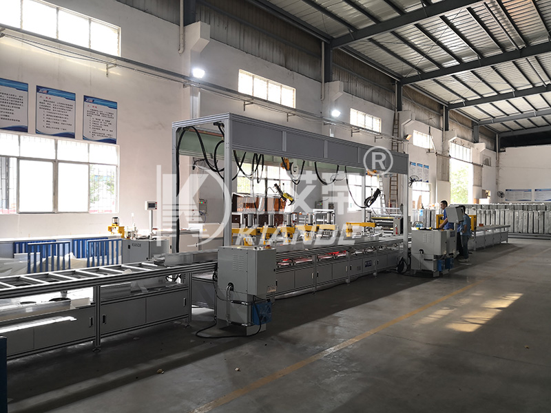
A successful riveting operation hinges on achieving a zero-gap mating of the housing halves before the rivet ever pierces the metal. Precision clamping serves as the prerequisite for this outcome within any Busduct Production Line. Success criteria on the factory floor include the complete absence of material buckling, precise rivet hole alignment, and uniform pressure distribution along the entire length of the extrusion. When clamping forces are perfectly calibrated, the self-piercing or solid rivets lock the metal layers together without creating internal stress fractures. This mechanical harmony ensures the enclosure maintains its structural integrity under heavy electrical loads.
Manufacturers often weigh riveting against bolted or welded housing joints. Welding introduces extreme heat, which warps thin-gauge aluminum and destroys pre-applied protective coatings. Bolted joints require manual torqueing, introduce protruding hardware, and frequently loosen under continuous 60Hz vibration. Riveting offers superior resilience against thermal cycling and mechanical vibration. Its success relies entirely on the precision of the pre-rivet clamping phase. If the clamping system fails to compress the housing halves completely, the rivet expands between the metal layers. This creates a weak, non-sealed joint that fails under minimal stress.
Accurate clamping directly influences how the busduct performs during site installation and operational lifespan. Poorly clamped housings lack structural rigidity. During a short-circuit event, the busbars experience massive electromagnetic repulsion forces. If the housing is poorly clamped and riveted, these internal forces can literally blow the enclosure apart. A rigidly clamped and riveted housing withstands these internal fault currents as well as external stresses from hanger supports, vertical support units, and beam clamps without twisting. Site contractors rely on beam clamps to secure the duct to steel structures. If the housing dimensions are skewed due to bad clamping, the mounting hardware will not sit flush, leading to unsafe load distribution.
The manufacturing impact of poor clamping extends far beyond simple aesthetic defects. Misalignment forces the riveting tool to strike off-center. This routinely causes drill bit breakage, damages the anvil, and results in scrapped aluminum or steel housings. Every millimeter of deviation increases the scrap rate. Consider the labor cost of rework. Drilling out a bad rivet, realigning the housing, and re-riveting takes ten times longer than the initial automated cycle. If the extrusion is damaged during rivet removal, the entire section must be scrapped or heavily salvaged.
Common defects resulting from poor clamping include:
Rivet Roll-Over: The rivet tail fails to flare correctly because the metal layers separated during impact.
Extrusion Cracking: Localized stress fractures occur when uneven clamping pressure forces the aluminum profile out of its natural geometry.
Gasket Pinching: Misaligned housing halves unevenly compress the internal weather seals, creating direct pathways for moisture ingress.
Phase Bar Scuffing: Internal conductors rub against the distorted housing interior, degrading the Mylar or epoxy insulation over time.
The mechanical force applied to the busduct housing determines the quality of the final rivet. Different production environments require distinct approaches to applying and maintaining this force. Selecting the appropriate mechanism for a busbar riveting machine dictates cycle times, maintenance schedules, and the physical limitations of the materials being processed.
Pneumatic clamping utilizes compressed air to drive cylinders, delivering rapid and uniform pressure application. The primary advantage of air-driven systems is their actuation speed. Cylinders deploy and retract in fractions of a second, making them highly efficient for continuous workflows. Operators can adjust the clamping force by regulating the air pressure via inline manifolds.
The best use case for pneumatic clamping involves high-speed, repetitive riveting of standard straight busduct sections made from standard-gauge aluminum. In these scenarios, the required holding force is moderate, and speed is the priority. Pneumatic systems have distinct limitations. They are highly susceptible to facility air pressure drops. If the compressor cycles or multiple machines draw air simultaneously, the clamping force can momentarily dip, leading to a loose rivet. To combat pressure drops, facilities often install dedicated accumulator tanks directly at the machine. This ensures a localized reserve of compressed air, guaranteeing that the final clamp of the shift hits with the exact same force as the first.
Hydraulic clamping employs pressurized fluid to deliver exceptionally high, sustained holding force. Unlike air, hydraulic fluid is incompressible. Once the clamp engages, it locks the housing halves together with immense, unyielding pressure. This eliminates any risk of material shift during the violent impact of the riveting process.
This system excels when processing heavy-duty enclosures and high-amperage busducts. When the housing rigidity actively resists standard pneumatic force, hydraulics provide the necessary muscle to force the metal flat. Factory environments with extreme temperature fluctuations can affect hydraulic fluid viscosity, requiring seasonal adjustments to maintain consistent clamping speeds. Despite this, when processing 14-gauge or 12-gauge steel housings, hydraulics remain the undisputed choice. The trade-offs include slower actuation speeds compared to pneumatics and a more complex mechanical footprint requiring pumps, reservoirs, and reinforced hoses.
Servo-mechanical clamping represents the highest tier of precision control. This method uses electric servo motors paired with ball screws or linear actuators to provide programmable, highly precise force and position control. Servo systems utilize closed-loop feedback, constantly monitoring the exact pressure applied to the housing and adjusting in real-time.
This technology is the optimal choice for high-mix production lines requiring frequent changeovers. Because the force is digitally controlled, operators can instantly switch from clamping heavy steel to thin-gauge aluminum without risking deformation. High-resolution encoders track the clamp position down to the micron. This means the system can detect if a foreign object, like a stray washer or metal shaving, is trapped between the housing halves before applying full tonnage, preventing costly scrap. It eliminates the pressure fluctuations of pneumatics and the maintenance mess of hydraulics, though it requires a higher initial capital expenditure.
| Clamping Mechanism | Primary Power Source | Force Consistency | Best Application | Primary Limitation | Maintenance Requirement |
|---|---|---|---|---|---|
| Pneumatic | Compressed Air (80-120 PSI) | Moderate (Subject to line drops) | Standard straight aluminum sections | Insufficient for thick steel plates | Air filter replacement, cylinder seal checks |
| Hydraulic | Pressurized Fluid (Up to 3000 PSI) | Extremely High & Rigid | Heavy-duty, high-amperage steel housings | Slower actuation, leak risks | Fluid level monitoring, hose inspections, pump servicing |
| Servo-Mechanical | Electric Servo Motors | Perfect (Closed-loop feedback) | High-mix lines, tight weather-proof tolerances | Higher initial CapEx and complexity | Ball screw lubrication, software calibration |
The degree of automation integrated into the clamping process directly impacts labor costs, production throughput, and quality control consistency. Manufacturers must align their equipment choices with their actual production volumes and the complexity of their product catalogs.
A manual busbar assembly machine relies heavily on operator intervention. Workers utilize manually actuated toggle clamps, screw vises, or simple lever arms to secure the housing before riveting. The primary advantage is the exceptionally low initial capital expenditure. Manual setups are highly flexible and require virtually no programming or complex maintenance.
The trade-offs are significant. Manual clamping introduces a high risk of human error. Operators may fail to tighten a clamp fully, resulting in uneven pressure application across the length of the busduct. As operator fatigue sets in throughout a shift, cycle times slow down, and defect rates rise. This approach is suitable only for prototyping, custom one-off sections, or ultra-low volume production runs where speed is not a factor.
In a semi automatic busbar assembly setup, the workflow becomes a hybrid of human dexterity and machine precision. The operator manually loads the housing halves and internal busbars into the jig. Once positioned, the machine applies automated pneumatic or hydraulic clamping at the push of a button or foot pedal. Only after the sensors confirm optimal clamping pressure does the operator initiate the riveting sequence.
This level of automation perfectly balances cost with repeatability. It significantly reduces operator fatigue by eliminating the physical strain of manual clamping. It improves alignment consistency. The automated clamps apply the exact same force every single time, ensuring better integration of joining units and maintaining strict dimensional tolerances across large production batches.
Fully automated systems remove the operator from the immediate assembly zone. These setups feature conveyor-fed systems with automated positioning sensors, synchronized multi-zone clamping, and robotic riveting heads. The housing moves into the cell, the clamps engage automatically based on barcode or RFID data, and the robotic heads execute the rivet pattern with sub-millimeter accuracy.
While this approach demands a high upfront cost and complex software integration, it delivers maximum throughput. Fully automated lines provide verifiable torque and pressure data logging for every single rivet, ensuring absolute traceability for quality assurance. Defect rates drop to near zero, making this the only viable option for mega-factories supplying large-scale commercial infrastructure projects.
Transitioning from manual to automated clamping requires a phased approach:
Profile Standardization: Audit all extrusion profiles to ensure they share common datum points for automated clamps to grip.
Cycle Time Analysis: Measure the exact seconds lost to manual toggle clamping versus the projected speed of pneumatic actuation.
Sensor Integration: Install pressure transducers on existing semi-automatic jigs to gather baseline force data before moving to fully robotic cells.
Pilot Testing: Run a limited batch of straight sections through the new automated clamps to verify zero-gap tolerances before attempting complex elbows.
Standard straight busduct sections represent only a portion of a complete power distribution system. Real-world installations require navigating around structural beams, changing elevations, and tapping into the main power feed. Manufacturing these complex geometries introduces severe clamping challenges.
Processing L-shapes, T-offs, and Z-bends through an elbow busbar assembly machine requires specialized tooling. You cannot utilize standard straight-line clamping jigs for these profiles. Elbows possess uneven weight distribution and complex centers of gravity. If clamped improperly, the cantilevered weight of the bend will twist the housing out of alignment. Riveting an elbow often requires off-axis tool approaches, meaning the clamping force must resist lateral pushback from the riveting head, not just vertical compression.
Busduct sections designed to house takeoff boxes or connect to vertical support units feature specialized cutouts and reinforced mounting points. Clamping these sections requires extreme care. The area around a plug-in window is structurally weaker until the rivet is set. Clamping fixtures must bridge these gaps without crushing the window frame. Ensuring flush riveting around these integration points is critical. If the housing bulges, the takeoff box will not seat correctly, creating a severe arc flash hazard during field operation.
To combat twisting and uneven pressure on complex geometries, manufacturers must deploy multi-axis clamping solutions. These custom, modular jigs support the busduct from multiple vectors simultaneously. While vertical clamps compress the top and bottom halves, horizontal clamps push inward to ensure the side profiles remain perfectly plumb. This multi-directional force locks the entire assembly in a rigid matrix, preventing any micro-movements during rivet insertion.
In a facility producing both straight runs and complex elbows, downtime is the enemy of profitability. The importance of quick-release clamping fixtures cannot be overstated. Operators must be able to switch between straight section jigs, elbow configurations, and specialized connection nodes in minutes, not hours. Utilizing modular clamping blocks with standardized mounting plates allows the factory to pivot production rapidly while maintaining the strict tolerances required for accurate riveting.
Effective modular clamping systems should include:
Quick-disconnect pneumatic fittings to swap air lines without hand tools.
Color-coded spacer blocks to match specific busduct amperage ratings.
Magnetic or detent-pin locking mechanisms for rapid jig alignment.
Non-marring urethane contact pads that can be replaced independently of the main steel clamp body.
Procuring a clamping system requires a strategic evaluation of how machine features translate directly into field performance. Engineering teams must look beyond basic specifications and analyze how the equipment supports overall compliance and scalability.
Every feature on a clamping system must correlate to a specific manufacturing outcome. Independent pressure zones allow a machine to apply varying levels of force along a single length of busduct. This feature directly eliminates micro-gaps in multi-piece housing assemblies where material thickness might slightly vary. Clamping systems equipped with pressure interlock sensors guarantee that the riveting head will not fire if the holding force drops below the required threshold, thereby preventing the creation of weak, shear-prone joints.
Manufacturing demands evolve. A clamping system must be evaluated on its ability to scale. Assess how easily a pneumatic system can be upgraded to servo-mechanical control without requiring a complete teardown of the existing line. Modular machine frames that accept bolt-on automation upgrades allow manufacturers to spread their capital expenditure over time. The clamping system must also communicate seamlessly with upstream roll-forming machines and downstream testing stations via standard industrial protocols like PROFINET or EtherNet/IP.
The ultimate test of a clamping system is whether the finished product passes rigorous certification testing. Clamping precision directly supports the manufacturing tolerances required to pass NEMA, UL, and IEC enclosure testing. For outdoor busducts, the housing must effectively shed water and prevent dust ingress. If the clamping system leaves a 0.5mm gap between the housing halves, capillary action will draw moisture directly into the live busbars. Precise clamping ensures that gaskets are compressed to their exact engineered specifications, guaranteeing IP65 or IP67 compliance and preventing catastrophic field failures.
Deploying new clamping technology introduces specific operational risks. Recognizing these failure modes early allows engineering teams to implement robust mitigation strategies, protecting both the equipment and the final product.
Applying excessive force is just as detrimental as applying too little. Over-clamping thin-gauge aluminum housings crushes the internal profile. This distortion compromises the fit of joining units and can damage the internal insulation wrapping the copper or aluminum conductors. Mitigation involves implementing servo-controlled force feedback systems that stop applying pressure the millisecond the target force is reached. For pneumatic systems, install precision digital pressure regulators on all air lines and lock them out to prevent unauthorized operator adjustments.
Insufficient holding force allows the metal parts to shift during the violent impact of riveting. This creates elongated holes and reduces the housing's ability to moderate temperature changes and mechanical stress. Under-clamped joints will eventually suffer from rivet shear. Mitigation requires utilizing multi-point clamping arrays to distribute force evenly. Integrate minimum pressure interlocks into the machine's PLC. If the sensor detects a pressure drop, the interlock instantly halts the riveting machine, forcing the operator to resolve the issue before producing a defective part.
Continuous metal-on-metal contact degrades clamping pads over thousands of cycles. As the pads wear down, alignment drift occurs, slowly pushing the rivet placement out of tolerance. Mitigation dictates specifying hardened tool steel for high-impact zones. For areas contacting the painted or anodized housing, use non-marring urethane contact pads. Establish a strict preventative maintenance schedule that mandates weekly calibration checks and monthly pad replacements based on cycle counts.
Audit your current production parameters, including daily volume, housing material thickness, and the ratio of straight-to-elbow sections, to determine the necessary clamping force.
Request comprehensive cycle time studies from equipment vendors based on your specific extrusion profiles to validate throughput claims.
Conduct a physical pilot run using sample housing materials to inspect the zero-gap tolerance and shear strength of the riveted joint.
Evaluate the vendor's modular tooling options to ensure the clamping system can adapt to future product line expansions without requiring entirely new machinery.
A: Optimal clamping pressure depends entirely on the housing material and thickness. Thin-gauge aluminum typically requires lower pressure, around 60 to 80 PSI on a pneumatic system, to prevent crushing the extrusion. Heavy-duty steel housings require significantly higher tonnage, often necessitating hydraulic systems. The exact pressure must compress the metal layers flush without causing structural deformation.
A: Straight sections use linear, top-down or side-to-side clamping jigs that apply uniform pressure along a single axis. Elbow sections require multi-axis clamping. Because elbows have uneven weight distribution and off-axis angles, custom jigs must support the bend from multiple vectors to prevent the housing from twisting during rivet insertion.
A: Yes, many manual machines feature modular frames that allow for retrofitting. Manual toggle clamps can be replaced with pneumatic cylinders and a basic foot-pedal actuation system. This upgrade significantly reduces operator fatigue and improves pressure consistency, though it will not provide the data logging capabilities of a fully automated system.
A: Housing deformation is primarily caused by over-clamping or misaligned tooling. If the pneumatic or hydraulic pressure exceeds the structural yield strength of the aluminum extrusion, the profile will crush. Deformation also occurs if the clamping pads are worn, causing uneven force distribution that warps the metal before the rivet strikes.
A: The IP rating relies on perfectly compressed gaskets and flush metal-to-metal contact. If a clamping method fails to hold the housing halves tightly together during riveting, micro-gaps form along the seam. These gaps allow capillary action to draw water inside, destroying the busduct's ability to shed water and causing electrical faults.
A: Clamping fixtures should undergo a visual inspection daily to check for pad wear and debris buildup. Formal calibration of the pressure sensors, such as pneumatic regulators or servo load cells, should occur monthly or quarterly, depending on cycle volume. Strict maintenance prevents alignment drift and ensures consistent riveting quality.

