
Views: 0 Author: Site Editor Publish Time: 2026-10-10 Origin: Site


In high-amperage power distribution, the integrity of a bolted joint relies entirely on the dimensional accuracy of its connection holes. Misaligned holes in copper or aluminum joint bars force operators to manually re-drill or force-fit connections on the shop floor. These forced adjustments reduce contact area, increase electrical resistance, and create severe thermal failure risks under load. Mitigating these risks requires moving away from manual layout methods. Evaluating how a modern Busbar Machine automates and verifies hole positioning is the first step in upgrading your fabrication capabilities. We need to look at the mechanics of CNC positioning, material clamping, and software integration to ensure strict NEMA or IEC compliance.
Precision Dictates Performance: Automated positioning eliminates human layout error, ensuring overlapping bars achieve maximum surface contact for optimal conductivity and electric bonding.
CNC is the Standard: Modern busbar fabrication equipment relies on multi-axis servo motors, linear guides, and CAD/CAM integration to achieve sub-millimeter hole placement accuracy.
Material Handling Matters: Accurate positioning isn't just about the punch; it requires robust clamping and feeding mechanisms to prevent material shift during joint conductor cutting and punching.
Evaluation Requires Holistic Analysis: Buyers must assess a machine based on software usability, tooling changeover speed, automated inspection capabilities, and sensor reliability, not just stated punching force.
Fabricating reliable electrical connections demands absolute dimensional control. Manual layout methods introduce unacceptable variance into the production line. A simple scribe line error translates into a misaligned connection point. You cannot afford these deviations in high-amperage switchgear. Establishing a technical baseline for acceptable joint bar processing requires defining strict success criteria. Every punched hole must align perfectly with its mating component. The fabrication process must deliver this accuracy repeatedly, regardless of operator fatigue or material batch variations. When we assemble a 4000A main tie main switchboard, a 2mm deviation across a four-hole splice plate stops the entire job.
Hole alignment directly dictates bolt torque distribution across the overlapping area. When holes align perfectly, bolts drop in without resistance. Operators apply the specified torque evenly. This even torque creates uniform clamping pressure. Uniform pressure maximizes the surface contact area between the two busbars. Maximum contact area minimizes electrical resistance across the joint.
Precise hole sizing and spacing accommodate essential hardware. Flat washers need sufficient clearance to sit flush against the copper surface. Belleville spring washers require a perfectly flat base to maintain long-term clamping force. If a hole is off-center, the bolt enters at a slight angle. The washers cannot seat properly. This uneven seating compromises the spring tension over time. As the joint undergoes thermal cycling, the loose connection degrades rapidly.
Off-center holes create severe thermal consequences. A misaligned bolt reduces the effective cross-sectional area of the connection. Electrical current crowds into the remaining contact points. This current crowding generates localized hot spots. Elevated temperatures accelerate oxidation on the copper or aluminum surfaces. Oxidation acts as an insulator, driving resistance even higher. This thermal runaway cycle ultimately leads to catastrophic joint failure under heavy load. I have seen switchgear melt down simply because a fabricator rushed a manual punch job and forced a Grade 5 bolt through a misaligned hole.
Achieving success in joint bar hole punching requires meeting strict baseline tolerances. Standard switchgear and panelboard assembly generally demand hole position tolerances of +/- 0.1mm to 0.2mm. Hole diameter tolerances must remain equally tight to prevent bolt slop. These tolerances ensure that multi-bolt joints assemble seamlessly on the factory floor.
Repeatability across high-volume production runs is absolutely necessary. You must guarantee that the first piece matches the thousandth piece perfectly. Poor repeatability leads to missing bolts during final assembly. Assemblers might resort to forced fits, damaging the bolt threads or distorting the busbar. Consistent positioning eliminates these assembly bottlenecks and ensures reliable field performance.
Modern fabrication systems utilize a blend of mechanical and digital technologies to drive positioning accuracy. Mechanical systems handle the physical movement and stabilization of heavy raw materials. Digital systems provide the intelligence, tracking coordinates and verifying final placements. Understanding these categories helps you evaluate the true capability of any processing center.
X and Y-axis servo-driven feeders represent the heart of automated positioning. These high-torque servo motors move the heavy copper or aluminum stock to exact coordinates. They drive precision ball screws or rack-and-pinion gear systems. The controller sends rapid pulse signals to the servos, dictating speed and final position. This multi-axis movement allows the machine to process complex hole patterns without manual intervention.
Absolute encoders play a vital role in maintaining positional awareness. These sensors attach directly to the servo motors. They track the exact rotational position of the drive shaft at all times. Unlike incremental encoders, absolute encoders do not lose their position data during a power outage. Operators do not need to perform manual zeroing routines after a restart. The machine always knows exactly where the material sits.
Accurate positioning requires absolute material stability during the punching cycle. Hydraulic or pneumatic clamps secure the busbar firmly against the machine bed. Heavy copper bars require high-pressure hydraulic clamping to prevent micro-shifts. Lighter aluminum bars often use pneumatic clamps to avoid surface marring. These clamps engage milliseconds before the punch descends, locking the material in place.
Heavy-duty linear guideways maintain straight-line feeding throughout the process. Raw busbar stock can weigh hundreds of pounds. Moving this mass quickly creates significant lateral forces. Rigid linear guides absorb these forces, preventing the material from skewing off-axis. This straight-line stability is non-negotiable during joint conductor cutting and subsequent punching operations. If the bar kicks sideways during a cut, the subsequent hole coordinates will be entirely wrong.
Laser crosshairs provide excellent visual confirmation for semi-automated setups. Operators use these lasers to align custom punch marks quickly. The laser projects a sharp, visible grid directly onto the material surface. This allows for rapid manual positioning when processing one-off custom pieces or repairing damaged sections in the field.
Optical sensors handle edge detection and zero-point referencing automatically. As the material feeds into the machine, the sensor detects the leading edge. The controller uses this edge as the absolute zero point for all subsequent hole coordinates. This eliminates errors caused by inconsistent raw material lengths.
Automated vision systems perform post-process inspection. Cameras capture high-resolution images of the punched holes. The software analyzes these images to verify hole presence, diameter, and exact alignment. This instant verification ensures flawless electric bonding later in the assembly process. It catches broken punches or positioning errors immediately, preventing downstream assembly delays.
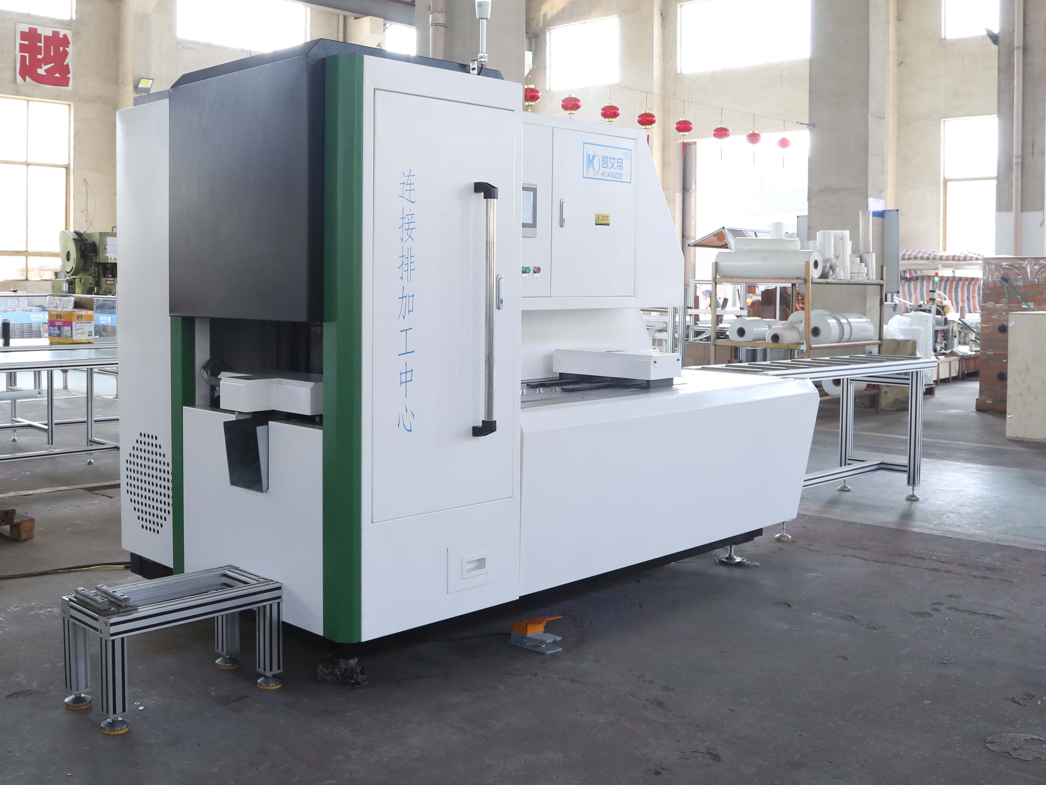
Assessing a machine requires a structured framework. You must evaluate specific features against your actual production outcomes. Raw punching force means little if the machine cannot place the hole accurately. Focus your evaluation on software usability, tooling precision, and material handling capabilities.
The machine controller must import 3D models directly into the punching program. Look for robust compatibility with standard formats like STEP and IGES. Direct import eliminates manual data entry errors. The programmer simply loads the file, and the software extracts the exact hole coordinates automatically. This seamless CAD/CAM integration drastically reduces setup times for complex switchgear designs.
Nesting software features maximize material utilization and accuracy. The software calculates hole coordinates based on the total material length and required bend allowances. When a busbar undergoes bending, the material stretches. Nesting software anticipates this stretch. It shifts the pre-punch hole coordinates slightly to compensate. After bending, the holes align perfectly with their mating components.
Automated tool changers maintain center-point accuracy across different hole sizes. Turret systems or linear tool magazines hold multiple punch-and-die sets. The machine rotates or slides the required tool into the active punching station. High-quality tool changers use precision locking pins to ensure the punch aligns perfectly with the die axis every time.
Proper die clearance prevents material distortion around the hole. The clearance between the punch and the die must match the material thickness and hardness. Incorrect clearance causes the material to roll over or tear. This distortion creates an uneven surface, preventing washers from seating flat. Operators must follow strict clearance charts when setting up the tooling.
Sharp tooling and correct clearances prevent micro-cracking and edge corrosion. A dull punch forces its way through the metal, creating microscopic fractures along the hole edge. These micro-cracks trap moisture and atmospheric contaminants. Over time, this leads to localized edge corrosion. Corrosion degrades the joint's electrical integrity, increasing resistance and heat generation.
Machines must address the different positioning requirements for copper versus aluminum. Copper is dense and requires higher punching force. Aluminum is softer but prone to galling and sticking to the punch. Operators must adjust clamping pressure and stripping mechanisms accordingly. Reliable busbar fabrication equipment must offer programmable parameters to handle these varying material characteristics smoothly.
Raw stock rarely arrives perfectly straight. Machines must compensate for slight bowing or imperfections. Advanced feeders use floating clamps that adapt to minor material curves. The optical sensors map the true edge of the bowed material. The controller then recalculates the hole coordinates dynamically, ensuring the final pattern remains accurate relative to the actual material geometry.
Buyers must navigate conceptual trade-offs based on their specific operational scale. There is no universal solution. You must weigh upfront capital expenditure against long-term labor savings. You must also balance raw production throughput against the need for high-mix agility.
Fully automated CNC processing centers require a high upfront investment. They feature complex servo systems, automated tool changers, and advanced software. In high-volume environments, this investment pays off rapidly. The machine runs continuously with minimal operator intervention. The labor savings and drastic reduction in scrapped material quickly offset the initial capital expenditure.
A semi-automated busbar joint processing machine often proves sufficient for low-mix, custom fabrication shops. These machines use manual mechanical stops or simple digital readouts. They cost significantly less than fully automated CNC models. For shops producing low volumes of highly customized switchgear, the lower capital expenditure makes better financial sense.
Evaluation Criteria | Fully Automated CNC Machine | Semi-Automated Machine |
|---|---|---|
Initial Capital Expenditure | High investment required for servo motors and software | Lower, more accessible cost for basic mechanical setups |
Hole Positioning Accuracy | Sub-millimeter, highly repeatable across thousands of parts | Dependent on operator skill, fatigue, and manual setup |
Production Volume Suitability | Ideal for high-volume, continuous runs of identical parts | Best for low-volume, custom batches or field repairs |
Setup Time per Batch | Very fast (CAD import, automatic tool selection, and go) | Slower (requires manual stop adjustment and test punches) |
Operator Skill Requirement | Requires basic CNC software training and file management | Requires strong manual layout skills and blueprint reading |
Programming complex hole patterns on a CNC machine takes mere minutes. The operator imports the CAD file, selects the tooling, and starts the cycle. This rapid setup is highly advantageous for facilities handling frequent design changes. The automated positioning system adapts to new coordinates instantly without any physical retooling.
Mechanical jigs and manual stops require significant physical setup time. The operator must measure, adjust, and lock down the stops for every new hole pattern. This process is slow and prone to human error. However, for extremely simple, one-off cuts or punches, a skilled operator might process a single bar faster on a manual machine than taking the time to program a CNC file.
Adopting advanced positioning technology introduces real-world challenges. You cannot simply plug the machine in and expect perfect results. Hardware requires maintenance. Software requires competent users. Recognizing these implementation risks allows you to build effective mitigation strategies before the machine arrives on your floor.
Operators accustomed to manual layout often struggle with modern CNC interfaces. They understand the metal but lack experience with digital coordinate systems. This knowledge gap leads to programming errors. Programming errors result in scrapped material and missed production deadlines. The transition from tape measures to touchscreens can cause significant friction on the shop floor.
Mitigate this risk by prioritizing vendors who offer comprehensive on-site training. Do not rely solely on user manuals. Ensure the machine features an intuitive, highly visual touchscreen UI. The software should display a 3D simulation of the punching process before the machine moves. Establish a robust technical support channel with the vendor to resolve early programming questions quickly.
Industrial environments are harsh. Copper punching generates fine, abrasive dust. This dust settles on optical sensors, blinding them. It works its way into linear bearings and ball screws, degrading the lubrication. Over time, this mechanical wear causes the positioning system to drift. A machine that started with 0.1mm accuracy might slip to 0.5mm accuracy within a year if neglected.
Implement strict preventative maintenance schedules immediately. Operators must clean optical sensors and laser lenses daily. Specify machines equipped with fully enclosed linear guides to keep copper dust out of the bearings. Utilize automated lubrication systems that deliver exact amounts of grease to the ball screws at regular intervals. Regular calibration checks ensure the absolute encoders maintain their true zero reference.
When a previously accurate machine starts punching off-center, operators must diagnose the root cause systematically. Do not immediately adjust the software offsets. First, inspect the physical clamping mechanisms. A worn hydraulic clamp pad allows the copper bar to slip backward slightly as the punch makes contact. This slippage looks like a software coordinate error but is entirely mechanical. Replace worn clamp pads and verify hydraulic pressure gauges before touching the CNC controller.
Inspect the physical clamping mechanisms for worn hydraulic pads that allow material slippage.
Verify hydraulic pressure gauges to ensure the clamps are applying the specified holding force.
Check the punched slug for an uneven shear zone, which indicates tool deflection from a dull punch.
Allow raw copper stock to acclimate to shop temperatures to prevent thermal expansion during processing.
Recalibrate the absolute encoders on the servo motors if mechanical slippage is ruled out.
Long copper busbars expand and contract with ambient temperature changes. If you pull a 20-foot copper bar from a freezing storage yard and immediately process it in a heated shop, the material will expand during the punching cycle. A hole punched at the far end of the bar will drift out of tolerance by the time the bar reaches room temperature. Allow raw material to acclimate to shop temperatures before processing long, multi-hole runs.
Tool deflection occurs when punching thick, hard copper alloys. If the punch is slightly dull, it will follow the path of least resistance, bending microscopically as it pierces the metal. This deflection pushes the hole center off the programmed coordinate. You can identify tool deflection by inspecting the punched slug. An uneven shear zone on the slug indicates the punch is bending. Replace the punch and die set immediately to restore positional accuracy.
Raw copper busbar is incredibly dense. A standard 20-foot length of 1/2-inch by 6-inch copper weighs hundreds of pounds. Feeding this mass into a punching station requires robust mechanical support. If the feeding mechanism drags or hesitates, the servo motors will register a position error. Roller tables must align perfectly with the machine bed to eliminate friction. We use heavy-duty polyurethane rollers to support the bar without scratching the conductive surface. Scratches create high-resistance points that degrade joint performance.
Surface integrity is just as important as hole placement. When the machine feeds the bar forward, the clamps must release completely. If a clamp drags across the copper, it gouges the metal. These gouges interfere with the flat seating of splice plates. Modern machines use synchronized lifting rollers. These rollers elevate the bar slightly during the feed cycle, ensuring it floats above the die block. Once the bar reaches the target coordinate, the rollers drop, and the clamps engage. This floating feed mechanism preserves the pristine surface finish required for optimal electrical contact.
Hole positioning does not exist in a vacuum. Most joint bars undergo bending after the punching process. The accuracy of the flat punch pattern dictates the success of the final bent component. If a hole is punched too close to a bend line, the bending process will distort the hole into an oval shape. Oval holes cannot accept standard bolts and washers, rendering the part useless.
Operators must calculate precise bend allowances before programming the hole coordinates. The neutral axis of the copper bar shifts during a bend. The outer radius stretches, and the inner radius compresses. CNC software uses K-factors to predict this material flow. By applying the correct K-factor for the specific copper grade and thickness, the software shifts the flat hole coordinates. After the press brake forms the part, the holes end up exactly where the assembly drawings dictate.
Proper sequencing prevents tolerance stacking errors. Always punch holes before bending whenever possible. Punching a flat bar is inherently more accurate than trying to position a pre-bent, three-dimensional shape inside a punching station. However, for complex Z-bends, you may need to punch certain holes after forming. This requires specialized 3D clamping fixtures to hold the bent part securely without distorting the existing angles.
Audit your current manual layout scrap rates to establish a baseline for acceptable material waste.
Request a live demonstration from equipment vendors using your facility's specific CAD files to verify software compatibility.
Implement a daily cleaning schedule for all optical sensors and laser lenses to prevent copper dust buildup.
Establish a strict punch-and-die replacement protocol based on cycle counts rather than waiting for visible tool wear.
A: The machine uses integrated software to translate imported CAD models into exact X and Y-axis coordinates. The controller sends these coordinates to the servo motors. The software automatically accounts for material thickness, tool offsets, and bend deductions, ensuring the final hole placement is perfectly accurate after all processing steps.
A: Typical industry tolerances range from +/- 0.1mm to 0.2mm. This tight tolerance ensures proper bolt alignment across multiple overlapping bars. It accommodates flat washers perfectly and guarantees maximum surface contact, which is essential for minimizing electrical resistance in high-amperage joints.
A: Yes, modern machines process both materials effectively. Operators must adjust the punch-and-die clearances to match the specific material thickness and hardness. They must also modify the clamping pressure and stripping force to account for the differences in yield strength between copper and softer aluminum alloys.
A: Automated machines utilize heavy-duty hydraulic or pneumatic clamps. These clamps engage milliseconds before the punch strikes, locking the material firmly against the machine bed. Rigid linear guideways provide additional lateral support, preventing the heavy metal stock from shifting or skewing off-axis during the high-force punching cycle.
A: Routine maintenance is critical for sustained accuracy. Operators must clean optical sensors and laser lenses daily to remove abrasive copper dust. Maintenance teams must regularly lubricate linear guides and ball screws. Technicians should periodically calibrate the servo drives and verify the machine's zero-point references against a known physical standard.
A: Lasers provide excellent visual verification and flexibility for custom, one-off, or semi-automated work. However, automated mechanical stops driven by servo motors offer superior speed and repeatability for high-volume production, as they remove the need for the operator to visually align every single punch.
A: Dull punches require excessive force to penetrate the metal. This causes material deflection, micro-cracking, and severe burring around the edge. These defects subtly alter the effective center of the hole and create an uneven surface. This prevents washers from seating flat, ultimately compromising the clamping force and joint integrity.

