
Views: 0 Author: Site Editor Publish Time: 2026-07-29 Origin: Site


Switchgear, transformer, and control panel manufacturing hit a hard bottleneck on the shop floor: fabricating copper and aluminum conductive routing. Relying on manual measurements across separate workstations drives up operational costs. Fragmented workflows cause high scrap rates, tolerance stacking errors, and long lead times. A single millimeter of deviation in a copper run compromises electrical clearances and forces manual rework during final assembly. Modern manufacturing requires a consolidated approach. A centralized Busbar Machine integrates cutting, punching, and bending operations into one controlled environment. Bringing these steps together tightens dimensional tolerances, reduces manual material handling, and cuts labor hours. You stop moving heavy copper bars between different machines and start processing them in a single, streamlined cell.
Workflow Consolidation: A multifunction busbar processing machine integrates cutting, punching, and bending into a single footprint, drastically reducing material handling time.
Precision and Repeatability: Upgrading to a digital busbar punching machine eliminates manual layout errors, ensuring exact hole placements for critical electrical connections.
Scalability vs. Footprint: Selecting between a 3 in 1 busbar machine and standalone CNC stations depends strictly on facility space, production volume, and changeover frequency.
Risk Mitigation: Proper implementation requires evaluating hydraulic reliability, tooling availability, and operator safety features before capital expenditure.
The baseline requirement for conductive routing fabrication is uncompromising accuracy. Components must emerge burr-free and dimensionally exact to meet strict electrical clearance, creepage distances, and international safety standards like IEC 61439 and UL 891. A dedicated busbar processing machine achieves these success criteria by executing several distinct manufacturing steps with high mechanical force and digital precision. We see this on the floor every day. When you eliminate the tape measure and the hand punch, your yield goes up.
Hydraulic shearing stations rely on immense downward force and precise blade clearance to sever thick conductive metals. The mechanical relationship between the upper and lower shearing blades directly impacts the cut quality. If the clearance is too wide, the metal bends and deforms before tearing. If it is too tight, premature blade wear occurs. Proper calibration ensures a clean, perpendicular shear across the entire width of the material.
Producing flat, burr-free cuts without generating material waste is vital for maintaining electrical integrity. We call this scrap-less cutting. Burrs or jagged edges act as focal points for electrical stress. They lead to arcing or corona discharge in high-voltage applications. Clean cuts ensure maximum surface area contact when bars are spliced or bolted together. You cannot afford gaps in a 4000-amp main bus splice.
Capacity limits for cutting operations depend heavily on the material type and its cross-sectional thickness. Copper is denser and requires more shearing force compared to aluminum. Standard hydraulic stations handle copper up to 12mm or 16mm thick. Aluminum of similar dimensions cuts with less resistance but requires sharp tooling to prevent edge galling.
| Material | Max Typical Thickness | Shearing Behavior | Blade Clearance Requirement |
|---|---|---|---|
| Copper (Cu) | 12mm - 16mm | High resistance, clean shear | Standard/Tight |
| Aluminum (Al) | 16mm - 20mm | Lower resistance, prone to galling | Slightly wider, requires sharp edges |
Creating mounting points and hardware clearances requires robust punching capabilities. Standard tooling accommodates round, oblong, and square profiles. You also use custom dies designed for specific hardware mounting requirements. These holes must align perfectly with corresponding components in the switchgear chassis to avoid assembly delays.
Transitioning from manual center-punching to a digital busbar punching machine fundamentally changes the fabrication workflow. Manual layout is prone to human error. A misread tape measure results in scrapped material. Digital systems utilize CNC coordinate positioning to move the material or the punch head to exact X and Y coordinates automatically.
Advanced punching stations incorporate laser pointers for visual verification, multi-tool turrets to hold various die sizes simultaneously, and automated material stops. These features drastically reduce setup time. Operators no longer swap dies manually for every different hole size. The elimination of manual layout marks ensures repeatable accuracy across hundreds of identical parts.
Operator loads the DXF file into the machine controller.
The CNC system selects the appropriate punch die from the turret.
Hydraulic clamps secure the copper bar in place.
The positioning system moves the bar to the exact X/Y coordinates.
The hydraulic cylinder actuates, punching the hole and stripping the slug.
Bending is the most complex step in the fabrication process due to the physical behavior of the metal. Equipment supports multiple bend types. You have standard flat bending for creating an L-shape. You have vertical or edge bending. You also use U-bending and Z-bending for creating offsets around internal cabinet obstructions.
Specialized bending operations handle space-constrained switchgear configurations. Axial twisting allows the conductive path to change orientation without requiring bulky bolted joints. You twist the bar up to 90 degrees along its longitudinal axis. This capability routes power through tight breaker compartments efficiently.
Achieving exact bend angles without trial-and-error scrap relies on digital angle encoders and automatic spring-back compensation. Copper and aluminum both spring back slightly after bending pressure is released. Modern controllers calculate this material-specific spring-back. They over-bend the metal by a precise fraction of a degree. The final resting angle matches the engineering drawing perfectly.
Secondary operations elevate the quality and safety of the final component. Integrating chamfering or filleting to round off sharp edges is mandatory for high-voltage insulation applications. Sharp 90-degree corners create concentrated electrical fields. These fields degrade surrounding insulation over time or trigger corona discharge. Rounding these edges mitigates localized electrical stress.
Embossing and coining operations improve the physical contact surface area at connection points. You apply high pressure to flatten and texturize the joint area. The machine minimizes microscopic surface irregularities. This reduces contact resistance. It ensures efficient current transfer and prevents dangerous heat buildup at bolted connections.
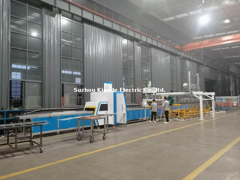
Selecting the right equipment requires comparing the structural differences between consolidated multi-station units and dedicated single-task machines. The optimal choice depends entirely on your facility layout, production volume, and the frequency of part changeovers. You have to look at your floor space and your daily tonnage requirements.
The 3-in-1 architecture consolidates cutting, punching, and bending stations onto a single heavy-duty chassis. A 3 in 1 busbar machine allows operators to process a raw length of copper through all necessary fabrication steps without moving the material across the factory floor. You load the bar once and perform all operations.
A structural distinction exists between single-pump and multi-pump hydraulic systems within these consolidated units. Single-pump machines route hydraulic pressure to one station at a time. Operations must occur sequentially. Multi-pump systems feature independent hydraulic circuits for each station. They allow up to three operators to cut, punch, and bend simultaneously without pressure drops or interference.
For mid-sized panel builders, the footprint-to-output ratio of a consolidated unit is highly advantageous. It delivers the capabilities of three separate machines while occupying a fraction of the floor space. It streamlines the workflow in environments where square footage is at a premium.
High-volume, continuous-production environments benefit from dedicated single-station CNC machines. When manufacturing standardized switchboards in mass quantities, having a standalone automated punching line feeding into a standalone automated bending cell maximizes throughput. You keep the material moving in a straight line.
Dedicated machines offer faster cycle times for their specific task compared to a multifunction busbar processing machine. They require significantly more floor space and automated material handling systems like conveyors to move parts between the separate stations efficiently. You only go this route if you are processing thousands of identical parts per week.
| Feature | 3-in-1 Consolidated Machine | Dedicated Single-Station CNC |
|---|---|---|
| Floor Space Required | Minimal (Compact footprint) | Extensive (Requires multiple cells) |
| Throughput | Moderate to High | Very High (Continuous flow) |
| Flexibility | Excellent for high-mix, low-volume | Best for low-mix, high-volume |
| Operator Requirement | 1 to 3 operators | Often fully automated |
To make an informed equipment decision, you map specific machine specifications directly to your manufacturing key performance indicators. You look at yield rates, machine uptime, and direct labor costs. You do not buy a machine based on a brochure; you buy it based on how many pounds of copper it can process per shift without errors.
Direct CAD/CAM integration transforms how engineering data reaches the shop floor. The ability to import .DXF, .DWG, or .STEP files directly into the machine controller eliminates manual data entry. Operators load the file. The machine generates the required punch coordinates and bend sequences automatically. This stops operators from fat-fingering dimensions into a keypad.
The Human-Machine Interface serves as the control center for the operator. High-quality HMIs provide real-time diagnostics, visual part previews, and tool life tracking. By monitoring the number of punch strokes, the system alerts maintenance personnel when a die requires sharpening. This prevents poor cut quality and unexpected downtime.
Automated nesting software enhances material yield. By analyzing the required parts for a specific job, the software calculates the most efficient way to cut them from standard lengths of raw material. It minimizes copper and aluminum offcut waste. You throw less money into the scrap bin at the end of the week.
The physical properties of copper and aluminum dictate how the machine handles them. Copper is highly ductile but prone to work hardening. It requires significant tonnage and exhibits noticeable spring-back during bending. Aluminum is softer and more prone to galling. Material sticks to the cutting or punching tooling if you are not careful.
Processing these materials requires specialized tooling geometries and appropriate lubrication strategies. Punch dies used for aluminum feature different clearance tolerances and coatings to prevent material adhesion. Modern controllers adapt to these differences. They allow operators to select the material type. This dynamically adjusts the hydraulic pressure profiles and spring-back compensation algorithms.
The hydraulic system is the driving force behind all fabrication steps. Pump quality, reservoir cooling systems, and cylinder tonnage dictate the maximum processing thickness. They also dictate the machine's ability to operate continuously under heavy loads. Inadequate cooling leads to fluid degradation and pressure loss during extended shifts. Hot oil means slow cycle times.
Hydraulic stability directly impacts bend angle consistency and punch speed. If the hydraulic pressure fluctuates, the bending cylinder fails to reach the exact programmed depth. This results in inconsistent angles. A robust, well-maintained hydraulic circuit ensures that the first bend of the day is identical to the last bend of the day.
In high-mix, low-volume production environments, setup time consumes a massive portion of the workday. The mechanics of quick-release tooling, simple punch die alignment, and rapid bending radii changes are critical for maintaining high overall equipment effectiveness. You need to swap dies in seconds, not minutes.
Slow changeovers carry a heavy operational cost. If an operator spends twenty minutes swapping dies and recalibrating the bending station for a new part profile, that is twenty minutes of lost production. Machines designed with quick-change turrets and drop-in bending pins drastically reduce this non-value-added time.
Upgrading your processing capabilities involves analyzing the financial and operational trade-offs. You ensure the investment aligns with your long-term manufacturing goals. You look at the hard numbers on the shop floor.
Evaluating the upfront cost of fully automated CNC equipment requires comparing it against the ongoing expenses of manual fabrication. Manual processes incur high labor costs. They increase scrap rates due to human error. They result in slower overall throughput. You pay for mistakes every time a worker misreads a drawing.
Calculating return on investment factors in material savings from minimized scrap. It includes the reduction in direct labor hours per completed panel. It accounts for the ability to take on larger contracts due to increased production capacity. The reduction in wasted copper alone justifies the capital expenditure over a relatively short period.
Future-proofing your investment means selecting equipment that grows with your business. Machines with modular tooling options or available software upgrade paths allow you to add capabilities as your product lines evolve. You might not need complex twisting today, but you will need it next year.
Consider the trade-off between purchasing a machine that meets your current peak capacity versus one that accommodates projected five-year growth. A higher-tonnage, fully automated machine requires more initial capital. It prevents the need for a secondary machine purchase when production volumes inevitably scale up.
Integrating heavy, high-tonnage machinery into an existing production line presents practical hurdles. You manage these proactively to ensure a smooth transition. You cannot just drop a machine on the floor and expect it to run perfectly on day one.
High-tonnage hydraulics introduce significant safety risks. You have pinch points, crushing hazards, and the potential for flying debris during punching operations. Strict adherence to safety protocols is non-negotiable. You have to protect your operators.
Required safety features include optical light curtains around the bending station. You need physical safety guards over shearing blades. You install easily accessible emergency stop buttons. You use dual foot-pedal controls that require the operator to be intentionally positioned during actuation.
The learning curve for CNC programming and machine operation requires structured, vendor-supplied training. Operators must understand how to run the software. They also need to perform basic troubleshooting and recognize signs of tooling wear.
Preventative maintenance prevents extended production halts. You cannot ignore the machine until it breaks. You have to follow a strict schedule.
Replace hydraulic fluid and filters every 2000 operating hours.
Sharpen punch dies after every 10,000 strokes to prevent burring.
Lubricate guide rails and moving components weekly.
Calibrate digital angle sensors monthly to ensure bending accuracy.
Establishing a relationship with a vendor that provides strong local support is essential. They guarantee tooling compatibility and maintain a robust inventory of spare parts. A machine sitting idle waiting for a replacement hydraulic valve severely impacts production schedules.
Audit your current scrap rates and calculate the exact labor hours spent on manual processing. Use this data to request a targeted technical demonstration and a formal time-study from a reputable machine manufacturer. Evaluate your facility layout to determine if a consolidated unit or dedicated stations fit your workflow best. Train your lead operators on CNC programming before the machine arrives on the shop floor.
A: Standard machines process copper and aluminum up to 12mm or 16mm in thickness. Heavy-duty models with higher hydraulic cylinder tonnage handle thicknesses up to 20mm. The maximum capacity is strictly dictated by the hydraulic tonnage and the structural rigidity of the shearing and punching frames.
A: Yes, provided the machine is equipped with a multi-pump hydraulic system. Multi-pump configurations feature independent hydraulic circuits for the cutting, punching, and bending stations. This allows three operators to work at the same time without experiencing pressure drops. Single-pump machines only allow sequential operation.
A: Digital machines use CNC coordinate axes to position material precisely. This eliminates the need for manual tape measuring and center-punch marking. Features like laser alignment guides and automated material stops ensure exact hole placement. It entirely removes human layout errors from the fabrication process.
A: Edge bending involves bending the material along its narrower edge rather than its flat width. It requires significantly higher hydraulic force and specialized, heavy-duty tooling. Not all base models support this operation. It is often an optional upgrade requiring specific machine configurations and higher tonnage cylinders.
A: Sharp 90-degree edges create concentrated electrical fields that lead to localized electrical stress. In high-voltage applications, this stress causes corona discharge or degrades surrounding insulation. Chamfering or rounding the edges smooths the electrical field. This ensures safer and more reliable power distribution inside the cabinet.
A: Copper is harder, requires more hydraulic tonnage to shear, and exhibits more spring-back during bending. Aluminum is softer but prone to galling and sticking to tooling. Processing aluminum requires different punch die clearances, specific lubrication, and adjusted spring-back compensation settings in the CNC controller.

