
Views: 0 Author: Site Editor Publish Time: 2026-10-09 Origin: Site


The shift toward aluminum in power distribution systems brings specific fabrication hurdles to the shop floor. High elasticity causes aluminum to spring back aggressively after bending. If you fail to compensate for this movement accurately, you produce out-of-tolerance components. This leads to high scrap rates, assembly delays, and compromised electrical clearances inside switchgear cabinets. Manual trial-and-error methods do not scale. They destroy margins in high-volume production environments where precision dictates project success. Achieving repeatable bends requires a deep understanding of the metallurgical behavior of the metal. You must leverage modern technology equipped with advanced stroke-based and algorithm-driven compensation mechanisms. This guide breaks down how a Busbar Machine handles these complex variables to deliver exact geometric profiles consistently.
Material Variance: Aluminum has a lower ductility-to-strength ratio than copper, requiring a more aggressive overbend. You often bend to 95° to achieve a 90° resting angle.
Algorithmic Compensation: Modern CNC systems use embedded material databases and finite-element calculations to adjust stroke depth automatically for springback.
Tooling Geometry: Proper die selection and R-angle calculations prevent outer-radius cracking. Aluminum needs a K-factor multiplier of roughly 1.2x compared to baseline formulas.
Process Integration: Bending accuracy depends heavily on upstream precision. Integrating operations with a high-quality aluminum busbar cutting machine ensures consistent lengths and predictable stress distribution.
Elastic recovery happens the moment you remove bending force from the metal. During the downward stroke, the inner radius compresses while the outer radius stretches under extreme tension. Residual stresses cause the material to attempt a return to its original flat state. This physical reaction occurs as soon as the bending die retracts. The severity of this recovery depends on the specific alloy, its temper, and the grain direction of the extrusion. When the hydraulic ram releases pressure, the unyielding core of the metal forces the stretched outer fibers to contract. This mechanical reaction alters the final resting angle of the busbar.
Understanding the exact sequence of events during a standard bend cycle helps operators anticipate material behavior. The process follows a strict mechanical progression:
The punch contacts the material and applies downward force against the V-die.
The metal yields plastically, conforming to the specific angle of the tooling.
Internal stresses build up rapidly along the neutral axis of the busbar.
The punch retracts, releasing the applied mechanical pressure entirely.
The material undergoes elastic recovery, springing back toward its original flat shape.
The component settles into its final resting angle, determined by its modulus of elasticity.
Mechanical properties differ wildly between these two common conductors. Aluminum’s specific modulus of elasticity dictates a much higher springback angle. Its yield strength determines how it deforms under pressure. Copper offers higher ductility and behaves more predictably under standard tooling. To achieve a precise 90° bend, copper typically needs a 1° to 2° compensation angle. You bend it to 92°. Aluminum routinely requires a 3° to 5° compensation angle. You must bend it to 95° or more to hit that same 90° resting position. Fabricators must adjust their entire approach, tooling setup, and software parameters when switching materials.
Material Property | Copper (Typical) | Aluminum (Typical 6101-T6) |
|---|---|---|
Modulus of Elasticity | ~117 GPa | ~69 GPa |
Ductility | High | Moderate to Low |
Typical Overbend for 90° | 1° - 2° (Bend to 91°-92°) | 3° - 5°+ (Bend to 93°-95°+) |
K-Factor Multiplier | 1.0x (Baseline) | ~1.2x (Adjusted) |
Aluminum features a lower ductility-to-strength ratio compared to traditional copper profiles. This characteristic directly impacts the minimum bend radius required during fabrication. It increases the risk of outer-radius fracturing significantly. If overbending is not controlled, the metal will crack along the tension line. Fabricators balance the aggressive overbend needed for compensation against the material's tensile limits. Pushing the metal past its yield point degrades structural integrity. It also lowers the electrical conductivity of the final installation, creating hot spots in the switchgear. You must select tooling that respects the physical limits of the specific aluminum temper you are processing.
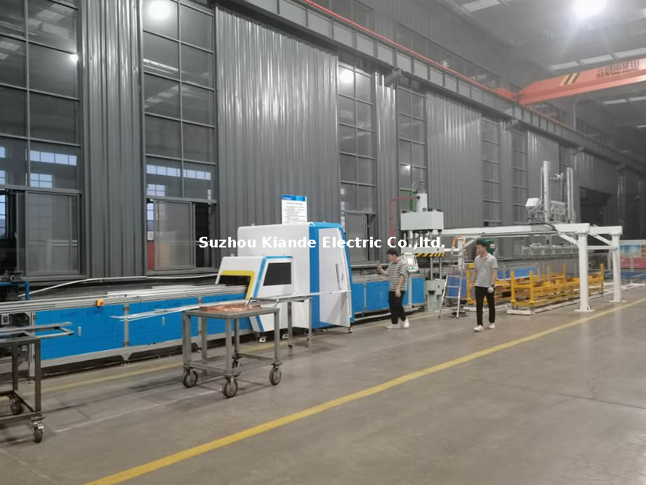
Mechanical compensation involves driving the punch deeper into the V-die. This physical process pushes the material past the target angle. It accounts for the calculated elastic recovery of the specific metal batch. Purely mechanical, open-loop overbending has severe limitations on the shop floor. It lacks real-time sensor feedback during the pressing cycle. This becomes problematic when dealing with high-strength extrusions where temper varies slightly from batch to batch. Variations in material temper lead to inconsistent results without dynamic adjustments. Operators using open-loop systems rely heavily on manual test bends to dial in the correct stroke depth before running production.
CNC controllers use pre-programmed material profiles to eliminate operator guesswork. They rely on finite-element analysis algorithms embedded in the operating system. These systems calculate the exact overbend angle required for specific grades of aluminum. Closed-loop systems utilize angle encoders or laser sensors mounted near the die. They measure the bend in real-time as the hydraulic ram descends. This allows the machine to adjust the stroke dynamically before releasing the pressure. It ensures absolute precision across varying material lots. The software continuously updates its compensation parameters based on the feedback from the optical sensors.
Specialized V-dies and punch radii are engineered specifically for aluminum conductor processing. They accommodate the larger required bend radii inherent to the metal. The R-angle heavily impacts springback severity and structural safety. You must match the punch radius to the material thickness precisely. This prevents cracking during the aggressive overbend phase. Standard copper dies often feature radii that are too tight for aluminum. Using improper tooling geometry leads to immediate material failure and rejected parts.
Material Thickness | Minimum Punch Radius (6101-T6) | Expected Springback Range |
|---|---|---|
1/4 inch (6.35mm) | 1/4 inch | 3.0° - 4.0° |
3/8 inch (9.5mm) | 3/8 inch | 3.5° - 4.5° |
1/2 inch (12.7mm) | 1/2 inch | 4.0° - 5.5° |
5/8 inch (15.8mm) | 5/8 inch | 4.5° - 6.0° |
Compare the upfront investment of closed-loop sensor-equipped machines against long-term operational returns. Closed-loop systems reduce scrap significantly by verifying angles during the stroke. They eliminate manual test-bending cycles that waste raw material and operator time. Look for an aluminum busbar processing machine that guarantees angle tolerances within ±0.3°. This accuracy should hold regardless of minor material batch variations. Open-loop systems require constant operator intervention. They struggle to maintain tight tolerances in high-volume production runs where material consistency fluctuates throughout the day.
Assess the machine's software interface carefully before procurement. A robust system allows operators to input specific aluminum grades easily. You can select 6101-T6 or 1350 alloys directly from a touchscreen menu. You specify tempers, widths, and exact thicknesses. The software then automatically generates precise compensation parameters based on historical data. This reduces operator error and speeds up setup times between different production runs. Advanced controllers also allow users to save custom profiles for proprietary extrusions. This feature proves invaluable when processing non-standard busbar shapes that require unique overbend calculations.
Bending accuracy relies heavily on the quality of the initial cut. Hole placements also affect structural integrity and stress distribution during the bend. Emphasize the importance of pairing the bending unit with precision upstream tools. An integrated setup using a reliable cutting unit and an aluminum busbar punching machine ensures burr-free edges. Exact datum points are necessary for predictable springback calculations. They ensure proper seating in the bending die. Misaligned cuts cause the busbar to shift during the pressing cycle, ruining the angle and forcing you to scrap the piece.
Variations in the extrusion process alter yield strength from one batch to another. Thermal treatment differences change how the metal behaves under mechanical stress. These factors alter the springback angle even within the same nominal material grade. You must account for these inconsistencies to maintain tight tolerances. A batch of 6101-T6 from one supplier may exhibit a 4° springback, while another shows 4.5°. Fabricators must track material origins and adjust machine parameters accordingly to prevent sudden spikes in rejected components. Documenting batch behavior helps operators anticipate required software adjustments before the first bend.
Mathematical adjustments are strictly required for aluminum fabrication. The K-factor represents the location of the neutral axis during bending. It shifts based on material thickness and the chosen bend radius. Fabricators often require a 1.2x multiplier for aluminum compared to standard copper formulas. This ensures accurate flat pattern development before any physical work begins. Wider busbars also distribute stress differently across the die. The machine must apply uniform pressure to prevent bowing or twisting along the width of the conductor.
Bend Radius to Thickness Ratio (R/T) | Standard Copper K-Factor | Adjusted Aluminum K-Factor |
|---|---|---|
R/T = 1.0 | 0.33 | 0.40 |
R/T = 1.5 | 0.38 | 0.45 |
R/T = 2.0 | 0.43 | 0.50 |
R/T > 2.0 | 0.50 | 0.50 (Neutral axis centers) |
Springback compensation alters the flat length of the busbar. The larger R-angle directly impacts these critical dimensions. Accurate length calculations are required before the material reaches the cutting stage. You must factor in the specific K-factor for aluminum to determine the exact cut length. This ensures final assembled dimensions align perfectly with the switchgear design. Incorrect flat pattern calculations lead to busbars that are too short to reach their connection terminals. This forces complete rework and wastes expensive material. Engineering teams must update their CAD software to reflect the specific tooling used on the shop floor.
Ambient temperature affects metal elasticity on the shop floor. Cold environments can make aluminum slightly more brittle during the morning shift. Heating the metal is not a viable solution for electrical components. DIY methods like using a torch and marker lines to anneal thick busbars are non-compliant. They structurally compromise the metal and destroy its electrical rating. Industrial-scale power distribution manufacturing requires strict adherence to cold bending protocols. You must rely on mechanical compensation rather than thermal manipulation to achieve the correct geometry.
The aggressive overbend pushes outer fibers closer to their tensile limits. This risks micro-fractures that degrade electrical conductivity over time. You must mandate strict adherence to minimum bend radius standards. Typically, this is 1x to 2x material thickness for standard aluminum profiles. Utilize polished, friction-reducing bending dies to minimize surface stress. Scratches on the outer radius act as stress concentrators. They encourage crack propagation during the overbend phase. Inspect your tooling regularly to ensure smooth surfaces. Implementing dye penetrant testing on the first article of a new batch helps identify invisible micro-cracks before full production begins.
Defect | Primary Cause | Corrective Action |
|---|---|---|
Outer Radius Cracking | Bend radius too tight for material thickness | Increase punch radius; verify material temper. |
Inconsistent Bend Angle | Material batch variation; worn dies | Perform test bends; recalibrate CNC compensation. |
Asymmetrical Springback | Misaligned cut edges; uneven die pressure | Check upstream cutting squareness; inspect die alignment. |
Surface Galling | Lack of lubrication; rough die surface | Polish V-dies; apply appropriate non-conductive lubricant. |
Over-reliance on software without understanding metallurgy leads to catastrophic errors. This often happens when introducing new material suppliers to the production line. Establish standardized test-bend procedures for your team. Run these tests for every new batch of aluminum received. This calibrates the CNC machine’s springback compensation parameters accurately. Operators must know how to read the metal. They need to identify signs of stress whitening or micro-tearing before running a full production batch.
Follow these exact steps for a proper test bend procedure:
Cut a sample piece from the new material batch using a precision saw.
Measure the exact thickness and width with digital calipers.
Input the dimensions and material grade into the CNC controller.
Execute a 90-degree test bend using the recommended die setup.
Measure the final resting angle with a precision digital protractor.
Adjust the compensation parameter in the software based on the measured deviation.
Run a second test piece to verify the new parameters hold true.
Worn dies alter the friction coefficient during bending. This directly changes the springback behavior and ruins precision. Dirty optical sensors in closed-loop systems cause inaccurate overbending calculations. Implement a strict preventative maintenance schedule immediately. Regular tooling inspection and sensor calibration are mandatory for consistent precision. Clean laser lenses daily to ensure accurate real-time angle measurements. Replace V-dies that show signs of galling or excessive wear. Tooling degradation is a primary cause of drifting bend tolerances. Keeping the machine clean prevents aluminum dust from interfering with the hydraulic stroke sensors.
Audit your current bending equipment to determine if it uses open-loop or closed-loop compensation mechanisms.
Update your flat pattern calculation formulas to include the 1.2x K-factor multiplier for all aluminum fabrication jobs.
Implement a mandatory test-bend protocol for every new batch of aluminum extrusions arriving at your facility.
Establish a daily cleaning schedule for all optical sensors and laser encoders on your CNC bending units.
A: Aluminum typically requires a 3° to 5° overbend to achieve a 90° angle. Copper generally requires only 1° to 2°. This difference exists due to aluminum's lower modulus of elasticity and distinct yield strength characteristics.
A: Modern CNC machines utilize embedded material databases and finite-element algorithms. They use real-time angle sensors to automatically adjust the hydraulic stroke depth during the bending cycle, ensuring the exact overbend is applied before releasing pressure.
A: Standard K-factor calculations often need to be multiplied by approximately 1.2 for aluminum. This accounts for its specific ductility-to-strength ratio and the unique neutral axis shift during deformation.
A: Localized heating alters the temper and reduces springback, but it is highly discouraged in industrial processing. It compromises the structural integrity and electrical rating of the busbar. Cold bending with mechanical compensation remains the strict industry standard.
A: Cracking occurs when the overbend angle exceeds the material's tensile limits at the outer radius. This is usually caused by using a bend radius that is too tight for the specific thickness and temper of the aluminum.
A: Yes. Using a high-quality cutting machine ensures square, burr-free edges. This allows the busbar to seat perfectly in the bending die, ensuring the CNC springback calculations are applied evenly across the material.

