
Views: 0 Author: Site Editor Publish Time: 2026-09-15 Origin: Site


Aluminum possesses only about 60% of copper's conductivity. To achieve equivalent ampacity, you must use a significantly larger cross-section. On the fabrication floor, this dimensional difference creates massive material handling bottlenecks. Processing mixed batches of copper and aluminum busbars traditionally forces operators to perform manual retooling. They have to manage separate storage racks and deal with frequent machine stoppages to accommodate varying widths, thicknesses, and weight profiles. These manual interventions kill production efficiency and increase the risk of dropping or damaging material.
Moving to an automated architecture requires understanding exactly how a modern Busbar Storage Loading System dynamically adapts to these dimensional and weight discrepancies. A properly integrated setup handles these variations without sacrificing cycle times, risking material damage, or causing cross-contamination. You need equipment that can transition from a heavy, narrow copper bar to a wide, light aluminum bar in consecutive cycles without human input.
Dynamic Tooling is Non-Negotiable: High-performance systems utilize programmable, servo-driven grippers and vacuum arrays to instantly adjust to the wider profiles of aluminum and the higher density of copper.
Integration Drives ROI: Seamless data handoffs between the loading system and the processing unit eliminate manual data entry and prevent material mismatch errors based on electrical volume resistivity requirements.
Surface Protection Matters: Aluminum’s lower tensile strength requires specialized handling pressure to prevent surface marring during automated transit.
Comprehensive Segregation: Advanced systems automatically manage inventory separation to prevent cross-contamination and mitigate galvanic corrosion risks both in storage and during the physical handling process.
Defining your baseline handling requirements starts by comparing the physical properties of C11000 copper against standard aluminum alloys like 6101-T6. Power distribution components rely heavily on these two metals. Their physical differences dictate the mechanical design of any automated handling equipment on your shop floor.
Copper is dense, heavy, and highly conductive. Aluminum is lighter, softer, and requires more physical volume to carry the same electrical load. These contrasting traits force automated loaders to operate across a very wide mechanical spectrum. If your gantry is only calibrated for one material, it will fail when handling the other.
| Material Property | C11000 Copper | 6101-T6 Aluminum | Automated Handling Impact |
|---|---|---|---|
| Conductivity | 100% IACS | ~61% IACS | Aluminum requires wider/thicker bars, demanding wide-stroke grippers. |
| Density | 8.89 g/cm³ | 2.70 g/cm³ | Copper creates heavy point loads; aluminum requires stability for wide profiles. |
| Tensile Strength | High | Lower | Aluminum is prone to surface scratching and edge deformation under high clamping force. |
| Oxidation Risk | Patina (slow) | Galvanic corrosion (rapid if mixed) | Strict physical segregation required in storage and handling zones. |
Electrical volume resistivity dictates the physical size of the raw material you bring into the facility. Because aluminum has a higher resistivity, it must be significantly wider or thicker to carry the same rated current as copper. This is commonly known in the industry as the 60% rule.
For example, if a specific switchgear application requires a 100x10mm copper bar to handle a 1000A load, the aluminum equivalent might need to be 160x10mm. This 60mm difference means fixed-width mechanical clamps will fail. The loading system must possess a wide, instantly adjustable gripping range. It must transition from picking up a narrow, thick copper bar to a wide, flat aluminum bar in consecutive cycles without an operator manually adjusting the gripper jaws with a wrench.
Handling these materials presents a unique mechanical paradox. Aluminum requires a larger cross-section for equivalent ampacity, but the final fabricated bar is still lighter than its copper counterpart. Copper's high density means even a compact bar carries significant mass.
The lifting mechanism must dynamically adapt to both extremes. When handling copper, the system manages high-payload, concentrated point loads. The motors and gantries must exert high torque to lift the dense material safely off the stack. When handling aluminum, the system manages wide-stance, lower-weight stability. The lifting motion must remain smooth to prevent wide, flexible aluminum bars from oscillating or swaying during transit across the factory floor.
Aluminum is highly susceptible to scratching and deformation. High clamping forces easily mar the surface of soft aluminum alloys. Copper is far more robust and can withstand aggressive mechanical gripping without showing signs of stress.
Automated systems require intelligent force feedback. If a system applies the same clamping pressure to aluminum as it does to copper, it will crush the edges of the aluminum bar. Surface defects compromise the electrical contact area during final assembly, leading to hot spots in the field. The handling equipment must modulate its grip strength based on the specific material being lifted.
Automated systems physically interface with raw materials using specialized end-of-arm tooling. The mechanics must adapt instantly to varying dimensions and densities. Engineers utilize several distinct approaches to solve this complex handling problem, moving away from static clamps to intelligent, sensor-driven arrays.
Rapid width adjustment is the most critical function of the lifting mechanism. Pneumatic clamps offer simple open-and-close functionality, but they lack precise width control. Programmable servo-grippers provide superior adaptability. Servo motors use internal encoders to adjust jaw width to the exact millimeter required for the scheduled bar.
Multi-zone vacuum suction systems offer an alternative for handling wide, flat aluminum bars. Vacuum systems lift the material from the top surface, eliminating the need for edge-clamping. This prevents edge deformation entirely. Advanced vacuum arrays activate specific suction zones based on the width of the bar, conserving air pressure and ensuring a secure hold.
| Tooling Type | Primary Advantage | Best Use Case | Limitation |
|---|---|---|---|
| Programmable Servo-Grippers | High precision and secure mechanical hold. | Heavy, narrow copper bars requiring strong lateral grip. | Can damage soft aluminum edges if force feedback fails. |
| Multi-Zone Vacuum Arrays | Zero edge contact, prevents surface marring. | Wide, flat aluminum bars. | Struggles with heavily oxidized or oily surfaces. |
Lifting heavy copper requires high torque. Lifting lighter aluminum with that same torque results in aggressive, jerky movements. These sudden motions can dislodge the material, cause it to swing dangerously, or create excessive wear on the gantry components.
Modern systems utilize load cells and variable frequency drives (VFDs) to solve this. Load cells instantly detect the weight of the material as the lift begins. The PLC processes this weight data and commands the VFD to automatically adjust the lifting torque. This ensures a smooth, controlled ascent regardless of the material density.
Blind automation leads to catastrophic machine crashes. The loading system must verify the physical material matches the production schedule before initiating a lift. Optical and laser profiling sensors scan the staging area continuously.
These sensors measure the exact width and thickness of the top bar in the stack. The system compares these physical dimensions against the ERP or MES data. If the schedule calls for a 160mm aluminum bar, but the sensors detect a 100mm copper bar, the system halts and alerts the operator. This verification ensures the correct material equivalent is always selected.
To understand how these mechanics work together, look at the standard automated lifting sequence executed by the PLC:
The gantry positions itself over the target cassette based on coordinates received from the storage management software.
The laser profiler scans the top layer of the stack to verify the width and thickness match the active job ticket.
Servo motors adjust the gripper jaw width to the exact millimeter, or the pneumatic manifold activates specific vacuum zones based on the scanned profile.
The Z-axis descends until proximity sensors detect physical contact with the material surface.
Load cells monitor the initial pull to calculate material weight, instantly adjusting the VFD torque for a smooth, controlled ascent.
High-mix changeovers introduce the risk of cross-contamination. Copper particulates are harder than aluminum. If copper dust embeds into the gripper pads, it will scratch the next aluminum bar the system handles. Furthermore, dissimilar metals in direct contact create a risk of galvanic corrosion.
Engineers design gripper pads and vacuum cups using non-porous, synthetic materials. These specialized polymers do not trap metal shavings or dust. They provide a clean, non-transferring interface. This simple mechanical choice prevents the transfer of dissimilar metals to aluminum surfaces during continuous automated cycles.
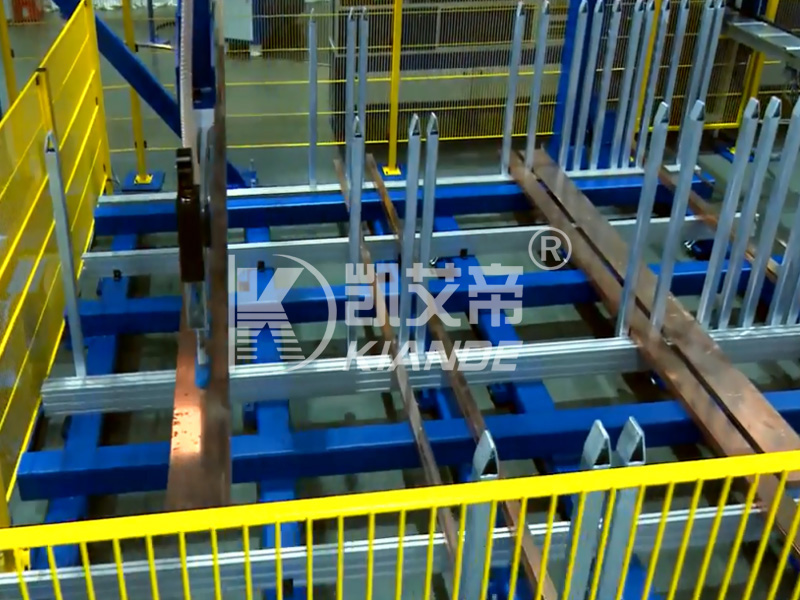
Storage architecture directly impacts loading efficiency and material integrity. A high-speed loading gantry is useless if the raw material is disorganized, buried under other stock, or inaccessible. Integrating the loader with an automatic raw material storage tower creates a seamless flow of inventory directly to the fabrication cell.
Traditional floor racking consumes massive amounts of square footage and requires forklift drivers to dig out specific bundles. Automatic storage utilizes vertical towers filled with variable-height cassettes. These cassettes maximize vertical space efficiently.
The system allocates taller cassette slots for thicker, bulkier aluminum stacks. It assigns shorter, heavily reinforced slots for highly dense, heavy copper stacks. A copper cassette might be rated for 2000kg but only take up 200mm of vertical pitch. An aluminum cassette might also be rated for 2000kg but require 400mm of vertical pitch due to the volume needed to hit that weight. This dynamic space allocation ensures the facility stores the maximum amount of raw material within the smallest possible footprint.
Software-managed physical separation in the storage tower is an absolute necessity. Copper and aluminum must never share the same physical storage space. Even trace amounts of moisture in the ambient factory air can act as an electrolyte between these two metals.
If copper and aluminum touch, galvanic corrosion begins immediately, degrading the contact surfaces before the bar is even cut. The storage software assigns dedicated cassettes for each material type. The automated stacker crane strictly enforces this segregation. It will not place a copper bundle into a cassette designated for aluminum. This mitigates the risk of galvanic corrosion before fabrication even begins.
Efficiency depends on staging the right material at the right time. The storage system does not retrieve cassettes randomly. It utilizes automated retrieval logic based on the upcoming production queue sent from the MES.
The software analyzes the next several hours of scheduled jobs. It pre-positions the required copper and aluminum cassettes near the loading extraction point while the current job is still running. This minimizes crane travel time. It optimizes the flow of mixed-metal batches, ensuring the loading gantry never waits for raw material to arrive from the top of the tower.
The critical transition from storage to active fabrication occurs at the infeed conveyor. The loading system must place the raw material precisely into the processing equipment. Any misalignment here causes severe downstream defects, resulting in scrapped material and wasted machine time.
The loading system must center bars of drastically varying widths onto the infeed conveyor. A compact 50mm copper bar and a wide 160mm aluminum bar require completely different placement coordinates. Accurate punching and bending depend on perfect centerline alignment.
The gantry utilizes its servo-driven axes to position the bar exactly over the center of the conveyor rollers. Once placed, automated pneumatic pushers fire from the sides. These cylinders gently tap the edges of the bar, pushing it flush against a fixed datum rail. This final mechanical verification ensures the material sits perfectly square before entering the CNC busbar processing machine.
Manual mechanical adjustments on the infeed table destroy automated efficiency. Operators should not need wrenches or handwheels to adjust side-guides when switching from copper to aluminum.
Modern systems eliminate these manual interventions entirely. The ERP/MES data passes directly to the processing machine via OPC UA or MQTT protocols. The system automatically adjusts the motorized side-guides based on the incoming material width payload. This zero-changeover automation allows continuous, uninterrupted production across mixed batches.
The feed rate of the loading system must match the processing speed of the CNC unit. Different materials process at different speeds. Softer aluminum alloys typically allow for faster cutting and punching speeds compared to dense copper.
The loading system communicates continuously with the CNC controller. If the processing machine speeds up for an aluminum batch, the loader accelerates its retrieval and placement cycles. If the CNC slows down for a complex copper bending sequence, the loader pauses. This synchronization prevents material starvation at the infeed and avoids dangerous bottlenecks on the staging table.
Loading efficiency directly dictates the throughput of final assembly. If the fabrication cell struggles to switch between materials, the downstream assembly stations will sit idle waiting for parts. Scalability requires seamless material transitions from the very first step of the process.
Modern electrical infrastructure demands flexibility. Facilities often require High-Mix, Low-Volume (HMLV) production runs. The automated system must switch between copper and aluminum on a per-piece basis without hesitation.
This agility supports custom project requirements. Different phases or runs within a single building may specify different conductor materials based on cost or weight constraints. For example, the phase conductors might be copper, while the ground conductor is aluminum. An agile loading system feeds the busduct assembly line exactly what it needs, exactly when it needs it, regardless of the material sequence.
Strict electrical codes require comprehensive material traceability. You must prove the origin, alloy type, and dimensions of every conductor installed in a critical power system.
The loading system acts as the first line of quality control. It utilizes barcode or RFID scanning capabilities at the storage cassette. It tracks the verified dimensions and material type through the entire fabrication process. This data attaches to the final assembly record, ensuring full compliance with industry standards and client specifications.
Deploying heavy automation involves significant operational risk. Understanding what can go wrong during deployment allows you to engineer preventative solutions before signing a purchase order and tearing up your factory floor.
Assessing the required floor space is the most common stumbling block. The storage tower, loading gantry, and safety fencing consume a large footprint. This is particularly challenging given the larger storage volume required for bulky aluminum inventory.
Many facilities underestimate the clearance needed for gantry travel and forklift access to the loading bays. A 12-meter bar storage tower needs significant ceiling height and heavily reinforced concrete floors. To mitigate this risk, conduct a comprehensive 3D spatial audit prior to procurement. Map the exact dimensions of the proposed automatic busbar loading system against your existing structural columns, overhead cranes, and aisleways.
Hardware is useless if it cannot communicate with your factory network. The risk of communication failures between the loading system's PLC and existing plant software is high. If the loader cannot read the ERP schedule, it cannot function autonomously.
Never assume plug-and-play compatibility. Require comprehensive API documentation from the vendor. Demand proven integration case studies showing successful data handoffs with your specific brand of MES or ERP software. Establish clear communication protocols and test the data payloads before installation begins.
Automated handling creates constant wear and tear on physical components. Vacuum cups degrade over time and become brittle. Gripper pads wear down, especially when handling sharp-edged copper bars continuously.
Ignoring this wear leads to dropped material and unexpected downtime. Establish a strict predictive maintenance schedule. Follow these steps to maintain handling integrity:
Inspect vacuum zones and synthetic pads weekly for embedded metal shavings.
Test the load cell calibration monthly to ensure accurate weight detection.
Clean the laser profiler lenses daily to prevent false width readings.
Check the servo motor encoders for positioning drift every quarter.
Stock critical wear parts in your local tool crib to ensure immediate replacement when degradation occurs.
An automated loading system is only as effective as its ability to seamlessly transition between different materials. It must handle the high density of copper and the larger dimensional footprint of aluminum without human intervention. It must accomplish this while strictly preventing cross-contamination and surface damage.
When evaluating solutions, prioritize vendors that offer servo-driven, sensor-verified gripping mechanisms. Insist on dedicated anti-galvanic storage protocols within the tower architecture. Ensure the vendor provides native software integration with your specific brand of CNC processing equipment to guarantee zero-changeover automation.
Take the following steps to begin your automation upgrade:
Audit your current production mix to determine your exact ratio of copper to aluminum processing.
Calculate the weekly labor hours currently lost to manual material changeovers and machine retooling.
Define your maximum required bar width and weight to establish strict baseline procurement specifications.
Conduct a 3D floor plan review to identify the optimal location for a vertical storage tower and loading gantry.
A: Systems rely on a combination of ERP/MES production data integration, barcode scanning at the storage cassette, and real-time weight/thickness verification using load cells and laser sensors.
A: Yes, provided the system uses programmable servo-grippers with a wide travel range or a multi-zone vacuum system that activates specific suction cups based on the programmed bar width.
A: No, provided the system is equipped with non-marring synthetic gripper pads or vacuum lifters, and the clamping force is automatically regulated via software when aluminum is selected.
A: By utilizing dedicated, software-assigned cassettes or trays for each material type, ensuring copper and aluminum never share the same physical storage space, and utilizing non-transferring gripper pads during the loading phase.
A: While capacities vary by manufacturer, industrial systems are typically engineered to handle payloads ranging from 500 kg to over 2,000 kg per cassette, with individual lifting gantries rated for the heaviest single copper bar in the facility's inventory.

