
Views: 0 Author: Site Editor Publish Time: 2026-10-08 Origin: Site


Moving from manual fabrication to automated busbar processing is a baseline requirement for switchgear and transformer manufacturers. You must maintain competitive margins and meet surging electrical demands. Rising copper and aluminum costs, shrinking tolerance margins, and a persistent shortage of skilled labor make traditional manual punching, bending, and cutting financially unsustainable. Facilities outsourcing this work leave significant profit on the table. Successfully scaling production requires deploying the right automated processing equipment. This applies heavily to shops already familiar with CNC workflows looking to insource fabrication. We break down how to assess machine capabilities, software integration, and implementation realities. You will learn how to ensure a high-return equipment investment without disrupting your current assembly lines.
Transitioning to a digital busbar punching machine and automated bending system drastically reduces expensive material waste and eliminates human error in complex assemblies.
A multifunction busbar processing machine consolidates floor space and workflow, but requires careful evaluation of cycle times, tooling changeovers, and CAD/CAM software compatibility.
True ROI hinges not just on raw machine speed, but on proprietary software integration, setup time reduction, continuous production capabilities, and long-term maintenance reliability.
Selecting the right equipment requires balancing current production volumes with future scalability, specific switchgear tolerance requirements, and facility constraints.
Manual measurement guarantees mistakes. An operator marking a copper bar with a tape measure and scribe will eventually misread a dimension. A miscalculated bend allowance or a punch hole off by a fraction of a millimeter results in immediate material scrap. Copper and aluminum are expensive raw materials. High scrap rates directly erode job profitability and inflate overall production budgets.
Labor bottlenecks present another massive financial drain. Skilled electricians and assembly technicians often spend hours on repetitive cutting and punching tasks. They should focus on complex electrical assembly, wiring, and quality control. Relying on manual processes limits your production capacity and extends lead times. You cannot compete for large-scale energy infrastructure contracts if your fabrication department cannot keep up with the assembly floor.
The downstream costs of inconsistent fabrication damage your reputation. Inaccurate bend angles and misaligned punch holes lead to forced fits during final assembly. Forcing a rigid copper conductor into place puts mechanical stress on insulators and breakers. This compromises electrical clearances and increases the risk of arc flashes. Finished panels frequently fail rigorous dielectric testing due to these forced fits. You end up with expensive rework, torn-down panels, and delayed deliveries to the job site.
Many electrical manufacturing shops operate standard CNC equipment for sheet metal or enclosure fabrication but continue to outsource their conductive component processing. Outsourcing leaves substantial profit margins in the hands of third-party vendors. It introduces severe supply chain vulnerabilities. A delayed shipment of fabricated copper halts your entire assembly line, leaving workers idle.
Modern automated systems have evolved to make insourcing highly accessible. Integrating a dedicated Busbar Machine allows manufacturers to capture previously lost margins. Bringing production in-house gives you absolute control over production schedules and quality assurance. You can execute rapid prototyping for custom switchgear designs without waiting weeks for a vendor to deliver a test piece.
Evaluating automation requires establishing strict baseline metrics. You must define target cycle times per part based on your current assembly demands. Acceptable tolerance deviations must be quantified. Modern high-density electrical panels typically require precision within +/- 0.1mm to ensure seamless integration.
Floor space utilization is another mandatory metric. You must assess the required reduction in setup times and operator intervention to justify the capital expenditure. Success means moving from a labor-intensive, multi-station manual workflow to a streamlined process. A single operator should manage continuous production with minimal tooling changeovers.
Manufacturers must choose between dedicated, single-process stations and integrated systems. Standalone machines separate the punching, bending, and cutting operations into distinct physical units. This setup allows simultaneous multi-operator processing. High-volume environments benefit from this when different components require different simultaneous treatments.
An integrated 3 in 1 busbar machine consolidates all three core functions into a single footprint. This approach drastically reduces material handling and minimizes Work in Progress (WIP) inventory. Operators do not need to transport heavy, 20-foot copper bars across the shop floor between distinct cutting and bending stations. Moving heavy material is dangerous and wastes valuable production time.
Evaluation Criteria | Standalone Machines (Separate Stations) | Integrated 3-in-1 Machines |
|---|---|---|
Floor Space | Requires large footprint for multiple machines and safety clearance. | Highly compact; maximizes facility floor utilization. |
Throughput | High parallel throughput (multiple operators working at once). | Sequential processing; excellent for complete part finishing. |
Material Handling | High; requires moving heavy bars between distinct stations. | Low; raw material enters, finished component exits. |
WIP Inventory | High; parts stack up between cutting, punching, and bending. | Low; single-piece flow eliminates intermediate bottlenecks. |
Power Requirements | Multiple heavy electrical drops required across the facility. | Single high-voltage drop simplifies installation. |
Evaluating throughput trade-offs dictates your purchase. While a multifunction busbar processing machine saves space and labor, you must ensure its sequential processing speed aligns with your overall assembly line demands. If you need to punch thousands of holes per hour while simultaneously bending hundreds of parts, standalone units might outpace an integrated system.
Legacy hydraulic manual presses rely entirely on operator skill for measurement, alignment, and execution. These systems are prone to human error and offer low repeatability. Semi-automated systems introduce digital readouts and programmable stops. They improve accuracy but still require significant manual material handling and physical positioning.
Modern electrical manufacturing demands fully CNC-driven equipment. A fully automated digital busbar punching machine features auto-feeding systems, automated tool changers, and continuous production loops. These systems integrate feeding, processing, and unloading without operator intervention. They run complex nested programs that maximize material yield and guarantee absolute repeatability across thousands of parts.
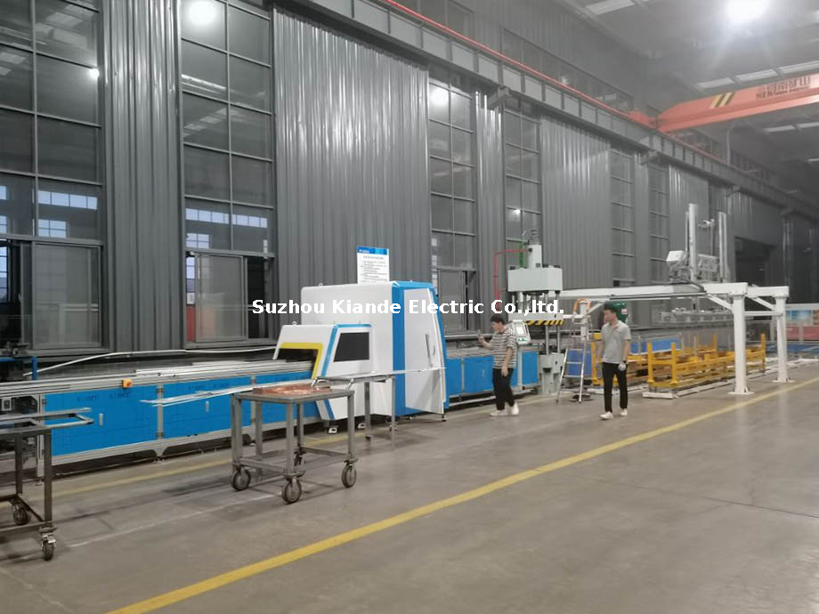
The drive system dictates the machine's precision and energy consumption. Traditional hydraulic systems provide immense force. However, they suffer from temperature-induced variations in hydraulic fluid. As the oil heats up during a long shift, viscosity changes, slightly affecting stroke consistency. Hybrid systems combine hydraulic power with servo-motor control for better accuracy. Fully servo-electric drive systems offer the highest precision, lowest energy consumption, and minimal maintenance. They execute exact stroke depths regardless of environmental conditions.
Automated spring-back compensation is a mandatory feature in bending operations. Copper and aluminum batches vary in hardness and tensile strength. When a machine bends a metal bar, the material naturally springs back slightly once the pressure is released. Advanced CNC machines utilize angle measurement sensors to detect this spring-back in real-time. The machine automatically applies a secondary micro-bend to ensure the exact programmed angle is achieved. This eliminates the need for manual test bends and scrap.
Hardware capabilities are only as effective as the software driving them. Seamless integration with standard electrical design software, such as EPLAN, SolidWorks, or AutoCAD, is non-negotiable for modern workflows. Manual programming at the machine pedestal is inefficient and introduces data entry errors. Operators typing coordinates into a keypad will eventually make a mistake.
Proprietary machine software must automatically translate 3D CAD models into executable machine code. This software calculates exact bend allowances based on material thickness and automatically plots punch coordinates. By flattening 3D designs into 2D processing paths, the software minimizes programming time. It drastically reduces production waste, ensuring the physical part perfectly matches the digital twin.
High-mix, low-volume production environments require rapid adaptability. Turret punch capacities determine how many distinct hole sizes and shapes can be executed without stopping the machine. You must evaluate die change mechanisms and the availability of specialized tooling for embossing, tapping, or offset bending.
Integrated finishing capabilities ensure electrical safety. Automated deburring, edge rounding, and chamfering remove sharp edges created during the cutting and punching phases. Smooth edges prevent electrical arcing and corona discharge in high-voltage applications. They also ensure safe handling for assembly technicians, reducing workplace injuries.
Rapid, tool-less changeovers directly impact overall equipment effectiveness. If an operator spends thirty minutes swapping heavy bending dies between jobs, machine uptime plummets. Quick-release tooling systems allow operators to transition between different copper profiles in minutes. You maintain high throughput even when processing diverse custom orders.
Processing copper requires different parameters than processing aluminum. Copper (specifically ETP - Electrolytic Tough Pitch) is denser and harder. It requires higher tonnage for punching and cutting. Aluminum (such as 6101 alloy) is softer but highly prone to galling. Galling occurs when friction causes aluminum particles to weld themselves to the steel punch die. This ruins the tool and creates jagged holes.
Operators must adjust punch-to-die clearances based on the material. Copper requires a tighter clearance to shear cleanly without dragging a burr. Aluminum requires a slightly larger clearance and specific tool coatings, like Titanium Nitride (TiN), to prevent material adhesion. Failure to swap tooling or adjust clearances when changing materials results in rejected parts and broken dies.
Processing Parameter | Copper (ETP) | Aluminum (6101 Alloy) |
|---|---|---|
Punch Clearance | Tight (approx. 5-8% of material thickness). | Moderate (approx. 10-12% of material thickness). |
Tooling Wear | High abrasive wear on cutting edges. | High risk of galling and material adhesion. |
Spring-back Factor | Low to moderate; highly predictable. | High; requires aggressive over-bending compensation. |
Lubrication Needs | Light vanishing oil for punching. | Heavy synthetic lubrication to prevent galling. |
Lubrication extends tool life and improves cut quality. Automated drop-lubrication systems apply a micro-dose of oil directly to the punch tip right before it strikes the material. For copper, a light vanishing oil works best because it evaporates, leaving the bar clean for assembly. Aluminum requires a heavier synthetic lubricant to create a barrier between the tool steel and the soft aluminum.
Bending dies also require attention. The V-die width must match the material thickness and desired bend radius. Using a narrow V-die on thick copper causes cracking on the outside radius of the bend. This cracking reduces the cross-sectional area of the conductor, creating a hot spot when the panel is energized. Operators must strictly follow tooling charts provided by the machine manufacturer.
Deploying heavy CNC machinery requires careful facility planning. You cannot simply drop a machine on the floor and plug it in. Proper installation guarantees long-term accuracy.
Verify Electrical Infrastructure: Power supply stability is paramount. Voltage fluctuations disrupt sensitive servo motors and CNC controllers. Verify that your electrical service can handle the machine's peak load requirements without voltage drops.
Reinforce the Floor: Industrial processing equipment generates significant operational vibration. The concrete slab must support the static weight of the machine and the dynamic forces of a 50-ton punch cylinder firing repeatedly.
Plan Spatial Logistics: Account for the automated feeding and unloading of long raw material bars. A compact machine still requires significant clearance on either end to accommodate standard 6-meter copper lengths safely.
Level the Frame: Use precision machinist levels to ensure the machine frame is perfectly flat. An unlevel machine causes binding in the linear guideways and premature wear on the drive components.
Transitioning from manual hand tools to complex CNC interfaces introduces a steep learning curve. Operators accustomed to manual measurement may resist digital workflows. Without proper adoption, the machine will not achieve its projected efficiency.
Conduct On-Site Training: Prioritize vendors that offer comprehensive on-site training. Operators need hands-on experience loading programs, changing dies, and clearing faults.
Establish a Tooling Library: Enter all physical punches, dies, and cutting blades into the machine's software library. The software must know exactly what tools are loaded to calculate accurate bend allowances and prevent collisions.
Run First-Article Inspections: Process scrap material first. Measure the finished parts with digital calipers and protractors. Compare the physical dimensions against the CAD model to verify machine calibration.
Implement Standard Operating Procedures (SOPs): Document every step of the setup and teardown process. Post these SOPs directly on the machine pedestal for quick reference.
Industrial machinery requires consistent maintenance to prevent catastrophic breakdowns. Neglecting basic checks leads to degraded precision and unexpected downtime. Operators must take ownership of daily maintenance.
Inspect Hydraulic Fluid: Check the fluid level and temperature gauge daily. Low fluid causes cavitation in the pump, destroying the internal seals.
Clean the Punch Turret: Remove copper and aluminum shavings from the punch and die holders. Debris buildup prevents the tools from seating properly, causing off-center holes and broken punches.
Grease Linear Guideways: Apply lithium grease to all moving rails and ball screws weekly. Lack of lubrication causes the auto-feeder to bind, resulting in inaccurate part lengths.
Empty the Scrap Bin: Do not let the scrap bin overflow. Backed-up scrap can jam the unloading chute and damage the cutting shear.
Sensors drift over time. The angle measurement sensors used for spring-back compensation require periodic recalibration. Maintenance technicians should use certified calibration blocks to verify the sensor's accuracy every six months. Additionally, hydraulic filters must be replaced annually to prevent microscopic metal contaminants from scoring the valve bodies. Local availability of spare parts and punch dies prevents long shipping delays when a component eventually fails.
Investing in a CNC processing system is a mandatory step for electrical manufacturers aiming to achieve precision at scale. Automation mitigates labor shortages, strictly controls material costs, and positions facilities to capitalize on growing sectors like renewable energy storage and data center infrastructure. Buyers must match the machine architecture directly to their primary production bottleneck. If floor space and WIP inventory are the main issues, an integrated multi-station system is optimal. If raw throughput volume across diverse part profiles is the goal, standalone automated CNC stations provide the necessary parallel processing power.
Implement the following concrete steps to move forward:
Audit your current scrap rates to establish a baseline for material savings.
Request a vendor time-study using your specific switchgear CAD files to verify real-world cycle times.
Evaluate your shop floor layout to ensure adequate clearance for loading 6-meter raw bars.
Verify that your design team's software exports directly to the machine's control interface.
A: A 3 in 1 busbar machine is a single manufacturing unit that performs cutting, punching, and bending operations on copper or aluminum busbars. It saves floor space, enables continuous production, and reduces manual material handling between stations.
A: CNC-controlled digital busbar punching machines typically achieve tight tolerances within +/- 0.1mm. This ensures exact hole alignment, which is mandatory for seamless switchgear, transformer, and energy storage assembly.
A: Yes, modern automated busbar machines fabricate both copper and aluminum. Operators must utilize specific tooling, adjust punch clearances, and modify bend radii based on the distinct tensile strengths and spring-back properties of each metal.
A: Daily maintenance includes checking hydraulic fluid levels, cleaning metal shavings from the punch turret, and lubricating linear guideways. Long-term maintenance involves replacing hydraulic filters and recalibrating angle measurement sensors.
A: Maximizing efficiency requires CAM software that translates 3D CAD models directly into machine code. This software automatically calculates bend allowances, punch coordinates, and optimal material nesting to minimize waste.
A: Advanced CNC machines use angle measurement sensors to detect how much the metal springs back after a bend. The machine automatically applies a secondary micro-bend to ensure the exact programmed angle is achieved without manual testing.

