
Views: 0 Author: Site Editor Publish Time: 2026-09-06 Origin: Site


In high-mix electrical manufacturing, accommodating variable busbar dimensions without causing production bottlenecks is a primary operational hurdle. Switchgear facilities process everything from heavy industrial panels to commercial solar arrays. Improperly adjusted wrapping settings for different busbar widths result in inconsistent insulation overlap, edge tearing, dielectric failures, and unacceptable scrap rates. When operators fail to recalibrate pitch and tension for a wider copper run, the Mylar film stretches thin at the corners. This compromises the creepage distance and guarantees a high potential test failure. Mitigating these risks requires a precise understanding of how tension, pitch, and material alignment must adapt to dimensional changes. It also requires selecting the right equipment—from manual stations to fully automated systems—to handle the required production mix and scale variations.
Precision is Non-Negotiable: Adjusting for busbar width requires recalculating film overlap percentages and adjusting feed angles to maintain consistent dielectric protection and meet creepage/clearance standards.
Design Dictates Machine Parameters: Conductor dimensioning, driven by ampacity and temperature rise requirements, directly influences the cross-sectional area and subsequent wrapping settings.
Equipment Dictates Changeover Speed: The choice between a manual setup and a programmable automated system directly impacts downtime during product changeovers.
Tension Control Prevents Failure: Wider busbars require different tension profiles to prevent Mylar or insulation film from wrinkling on the flats or tearing at the corners.
Integration Matters: Wrapping settings must be evaluated as part of the holistic manufacturing process, ensuring compatibility with upstream forming, jointing allowances, and downstream packing operations.
Electrical insulation forms the primary defense against catastrophic short circuits and phase-to-phase faults. You must establish strict baseline requirements for busbar insulation before adjusting any machinery on the floor. The wrapping process must guarantee optimal thermal dissipation while maintaining mechanical durability against vibration and thermal expansion. A successful wrap passes high-voltage dielectric tests without showing signs of leakage current. Achieving this requires precise control over the insulation film's overlap and tension. Any deviation in these parameters compromises the creepage and clearance distances mandated by international electrical standards.
To validate a successful wrapping setup, operators look for specific success criteria immediately after a width changeover. These criteria ensure the product will survive decades of field use under heavy electrical loads.
Zero visible micro-tears along the radiused edges of the conductor.
Consistent overlap percentage measured across a full three-meter length.
No air pockets or wrinkling on the flat surfaces of the busbar.
Passing a standard 5kV Hi-Pot test for sixty seconds without breakdown.
Conductor dimensioning dictates the required insulation thickness and the specific wrapping configuration. Copper and aluminum possess different conductivity levels, meaning an aluminum busbar requires a larger cross-sectional area to match the ampacity of a copper equivalent. This increased width changes the physical geometry the wrapping machine must navigate. Temperature rise limits further influence dimensioning. A conductor designed to operate at higher continuous currents will have larger dimensions, requiring wider insulation film or an adjusted wrapping pitch to ensure the material covers the expanded surface area without thinning out.
When switching from a 50mm wide copper busbar to a 100mm wide aluminum busbar, the wrapping head must travel a significantly longer path per revolution. The film spool experiences higher centrifugal forces, and the tension controller must compensate immediately. If the machine settings remain static during this material and size swap, the insulation will fail inspection.
Complex switchgear setups often utilize multi-conductor configurations to handle massive current loads. When designing these systems, engineers typically increase the cross-sectional area by five percent for each additional conductor to account for reduced cooling efficiency. This dimensional increase directly impacts the wrapping stage. Your equipment must adapt to these incremental width changes rapidly.
Failing to adjust the wrapping parameters for this five percent area increase results in over-tensioned film at the corners. The Mylar will stretch beyond its yield point, leading to micro-tears that eventually cause dielectric breakdown in the field. Operators must recalibrate the tension brakes and adjust the guide rollers to accommodate the slightly thicker and wider multi-conductor stack.
The insulation wrapping stage frequently becomes the primary constraint within a Busduct Production Line. When changeovers for different widths and scales are not streamlined, operators spend excessive time manually adjusting guide rollers, recalibrating tension brakes, and testing overlap ratios. This idle time reduces overall equipment effectiveness. If the upstream cutting and bending stations process copper faster than the wrapping station can insulate it, work-in-progress inventory piles up on the factory floor.
Streamlining width adjustments is an absolute necessity for maintaining continuous production flow. A facility processing ten different busbar widths per shift cannot afford thirty-minute changeovers. The mechanical adjustments must be standardized, repeatable, and verifiable to keep the line moving at target capacity.
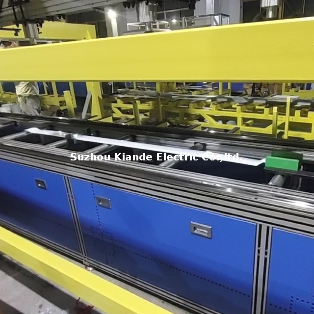
The physics of wrapping change dramatically as busbar width increases. Wider flats mean the insulation material travels a longer linear distance per revolution of the wrapping head. This geometry alters the tension applied to the film. As the wrapping ring rotates around a wide rectangular busbar, the distance from the center of rotation to the corner is significantly greater than the distance to the flat side. This creates a whipping effect, causing tension spikes every time the film passes over an edge.
Dynamic tension control becomes necessary to prevent the material from elongating excessively or suffering micro-tears at the corners. You must adjust the braking force on the film spool to maintain a constant pull regardless of the busbar's rectangular profile. A 200mm wide busbar generates massive centrifugal force on the film spool compared to a 50mm busbar, requiring a completely different baseline tension setting on the magnetic powder brake.
Maintaining a consistent 50% overlap is standard practice for ensuring adequate dielectric strength. The mathematical relationship between busbar width, wrapping head RPM, and linear feed speed determines this overlap. When you introduce a wider busbar to the machine, the circumference of the wrap increases. If the linear feed speed remains constant, the overlap percentage will drop, leaving dangerous gaps in the insulation.
To correct this, you must calculate the correct pitch. You either decrease the linear feed speed or increase the wrapping head RPM. Operators must recalculate these variables precisely for every width change to guarantee the insulation layers stack correctly across the entire conductor length. For example, achieving a 50% overlap with a 50mm wide film requires a precise pitch of 25mm per revolution. If the busbar width doubles, the machine must adjust its feed-to-rotation ratio to maintain that exact 25mm advancement.
| Busbar Width (mm) | Film Width (mm) | Target Overlap | Required Pitch (mm/rev) | Linear Speed Adjustment |
|---|---|---|---|---|
| 50 | 50 | 50% | 25 | Baseline |
| 100 | 50 | 50% | 25 | Decrease by 30% |
| 150 | 50 | 50% | 25 | Decrease by 50% |
| 200 | 50 | 50% | 25 | Decrease by 65% |
Wrapping settings must adapt to massive scale variations. Large power distribution busbars require heavy-duty film and slower processing speeds, while smaller, localized, or PC board-mounted busbars require delicate handling and rapid throughput. The machine's grip pressure, roller spacing, and feed motors must scale to match the mass of the conductor being processed.
Furthermore, machines must account for jointing areas. Busbars are rarely installed as single, continuous pieces. They require precise start and stop wrapping lengths so sections can be easily jointed, tightened, or dismantled in the field. If the wrapping extends too far, field technicians must manually strip the tough Mylar film, risking damage to the conductor. Automated systems use length-measurement encoders to stop the wrapping process exactly where the jointing allowance begins, typically leaving 50mm to 100mm of bare metal exposed at each end.
Proper material alignment prevents the film from wandering off the center axis during the wrapping process. A Mylar film forming machine plays a critical role here by pre-creasing or shaping the insulation material to match the specific busbar width before it enters the wrapping head. This pre-forming step ensures the film hugs the flat surfaces tightly, eliminating air gaps that could cause corona discharge.
Once the material reaches the wrapper, guide rollers and material feed angles must be physically or electronically adjusted. If the busbar is narrow, the guides move inward to prevent lateral shifting. If the busbar is wide, the guides expand. Incorrect alignment causes the film to track diagonally, resulting in uneven overlap and wrinkled insulation on the flat surfaces. Operators use feeler gauges to ensure the guide rollers provide exactly 0.5mm of clearance on either side of the conductor.
For entry-level production or highly customized one-off runs, a manual busbar packing machine offers a baseline solution. This approach relies entirely on operator skill to maintain tension and pitch. Operators physically push or pull the busbar through the wrapping ring while manually guiding the film. Changing widths requires physical tool changes and manual guide adjustments using wrenches and calipers.
The primary trade-off is the high labor cost and extended changeover times. A skilled operator might take thirty minutes to dial in the settings for a new busbar width. However, it provides maximum flexibility for highly specialized switch panel setups or complex geometries that automated systems struggle to grip. Shops handling low-volume, high-complexity orders often rely on these manual stations to process odd-shaped copper runs.
Mid-volume, moderate-mix environments benefit from stepping up to a semi-automated setup. This typically involves a motorized linear feed combined with manual wrapping head adjustments. You utilize a standardized busbar packing platform to stabilize the conductor as it moves through the machine. The motorized feed ensures a consistent linear speed, which drastically improves overlap consistency compared to purely manual methods.
This setup reduces operator fatigue and standardizes the throughput rate. However, width changeovers still require physical intervention. Operators must manually adjust the wrapping ring height, change the film spool tension, and realign the guide rollers for every new batch. While faster than a fully manual machine, a semi-automated platform still incurs fifteen to thirty minutes of downtime during a dimension change.
High-volume, high-mix facilities require a fully automated busbar insulation wrapping machine to remain competitive. These systems utilize servo-driven adjustments, programmable logic controllers, and recipe management systems via a touchscreen interface. Scalability and value are unmatched here. Operators simply select a pre-programmed busbar width from the menu.
The machine automatically adjusts the guide rollers, sets the dynamic tension profiles, and synchronizes the pitch based on the new dimensions. This drastically reduces changeover downtime from hours to minutes and completely eliminates the human error associated with manual calibration. Servo motors instantly adapt the linear feed rate to match the wrapping head RPM, guaranteeing a perfect 50% overlap regardless of the conductor's width or thickness.
| Equipment Type | Average Changeover Time | Tension Control Method | Operator Skill Required | Ideal Production Environment |
|---|---|---|---|---|
| Manual Packing Machine | 30 - 60 Minutes | Manual / Friction Brake | High | Custom one-offs, low volume |
| Semi-Automated Platform | 15 - 30 Minutes | Mechanical / Fixed Adjustment | Moderate | Mid-volume, moderate mix |
| Fully Automated Wrapping Machine | Under 5 Minutes | Dynamic Servo-Driven | Low (Menu Driven) | High-volume, high mix |
The physical process of widening or narrowing the feed guides requires strict attention to detail. First, halt the machine and lock out the power source. Loosen the locking collars on the lateral guide rollers. Slide the rollers inward or outward to match the new busbar width, leaving exactly 0.5mm to 1.0mm of clearance on each side. You must use a feeler gauge to verify this gap.
This clearance allows the conductor to pass smoothly without causing friction damage to the soft copper or aluminum surface. Tighten the collars securely. Next, adjust the vertical hold-down rollers to match the new thickness. The rollers should apply just enough downward pressure to prevent the busbar from vibrating during the wrapping cycle without crushing the applied insulation. If the rollers are too tight, they will mar the copper; if too loose, the busbar will chatter, causing uneven film overlap.
Adjusting the tension controller is the most critical step in a width changeover. If your machine uses a magnetic powder brake, you must adjust the voltage output to change the braking torque. Refer to the material specification sheet for the specific insulation film. Wider busbars require slightly higher baseline tension to keep the film flat across the broad surface, but the peak tension at the corners must not exceed the film's tensile strength.
If using a servo-tensioner, input the new busbar dimensions into the control panel. The system will automatically calculate the required dynamic tension profile, slacking slightly at the corners and tightening on the flats to ensure a perfectly smooth wrap. You must verify the spool spins freely without binding before initiating the first wrap cycle.
Never assume a changeover is successful without immediate validation. Run a test piece of the new busbar width through the machine. Conduct a thorough visual inspection for any wrinkles on the flat surfaces or micro-tears at the corners. Use digital calipers to measure the overlap distance; it must remain consistently at the specified percentage, usually 50%, across the entire length.
Finally, conduct an initial Hi-Pot test. Apply the specified test voltage across the insulation to verify its integrity. Connect the ground lead to the bare copper at the jointing end and run the high-voltage probe along the wrapped surface. If the test reveals leakage current, you must recalibrate the tension or pitch settings before running production. A failure here usually indicates the film was stretched too thin over the busbar edges.
Excessive idle time during mechanical adjustments directly reduces overall equipment effectiveness. In a high-mix environment where operators switch busbar widths multiple times a shift, a thirty-minute changeover destroys daily output targets. Mitigate this risk by implementing Single-Minute Exchange of Die principles on the shop floor.
Standardize all adjustment points with quick-release levers instead of bolts requiring wrenches. Color-code the guide rail positions for common busbar widths. For maximum efficiency, utilize machines equipped with digital recipe storage. This allows operators to recall exact tension, speed, and pitch parameters instantly, reducing the changeover process to a simple push of a button and a quick mechanical alignment. Training operators to perform these steps in a specific, choreographed sequence shaves minutes off every changeover.
Incorrect feed angles on a newly adjusted width frequently cause the Mylar film to track improperly. When the film wanders, it bunches up, causing severe wrinkling on the flats and extreme tension spikes that tear the material on the sharp busbar edges. Mitigate this by standardizing your setup procedures.
Ensure the busbar edges are properly radiused during the upstream fabrication process; sharp 90-degree corners will cut through insulation regardless of machine settings. Utilize laser alignment tools to verify the film spool is perfectly perpendicular to the busbar axis. For advanced setups, integrate automated edge-guiding systems that use optical sensors to continuously monitor and adjust the film tracking in real-time. If the film begins to drift, the sensor triggers a micro-adjustment to the spool angle, correcting the path before wrinkles form.
| Defect Type | Root Cause After Changeover | Immediate Corrective Action |
|---|---|---|
| Wrinkling on Flats | Film tracking off-center or tension too low. | Realign film spool axis; increase baseline brake tension. |
| Tearing at Corners | Tension too high or busbar edges not radiused. | Decrease peak tension; verify upstream edge milling. |
| Inconsistent Overlap | Linear feed speed mismatched with wrapping RPM. | Recalibrate pitch settings; check feed motor synchronization. |
| Hi-Pot Failure | Micro-tears or insufficient overlap exposing metal. | Verify 50% overlap with calipers; inspect corners for thinning. |
Audit your current changeover times to identify exactly how many production hours are lost weekly to manual width adjustments.
Track your scrap rates specifically related to dielectric failures and edge tearing after changeovers.
Standardize your busbar edge radiusing process upstream to ensure the wrapping machine receives a consistent profile.
Implement digital recipe management for all wrapping parameters to eliminate human error during high-mix production runs.
A: Wider busbars increase the circumference the film must cover per revolution. To maintain the required 50% overlap percentage, you must adjust the pitch by either slowing down the linear feed rate of the busbar or increasing the rotational speed of the wrapping head.
A: Yes. While copper and aluminum differ in ampacity and temperature rise, the wrapping machine settings are dictated primarily by the external dimensions and edge profiles. As long as the machine is adjusted for the physical width and thickness, it can wrap either material perfectly.
A: Automated wrapping machines use length-measurement encoders to track the busbar's position. Operators program specific start and stop points, allowing the machine to halt wrapping before the jointing ends. This leaves bare metal exposed so busbars can be easily jointed, tightened, or dismantled in the field.
A: A fully automated wrapping machine utilizing digital recipe storage and servo-driven adjustments typically completes a width changeover in under five minutes. This is a massive improvement compared to manual setups, which often require thirty to sixty minutes of physical calibration.
A: Preventing tears requires a two-step approach. First, ensure proper busbar edge radiusing during the upstream cutting and punching phases. Second, adjust the machine's dynamic tension control to slacken slightly as the film passes over the corners, preventing tension spikes.
A: A forming machine prepares the insulation material before wrapping. It pre-creases or shapes the flat Mylar film to perfectly match the specific busbar width. This ensures tighter adhesion, prevents air gaps, and helps the film track straight as it enters the wrapping head.
A: Compliance is based on the final product's dielectric strength and creepage distances, not the machine type used. A manual machine can produce compliant busbars, but it carries a significantly higher risk of human error, making consistent compliance harder to guarantee across large batches.

