
Views: 0 Author: Site Editor Publish Time: 2026-10-12 Origin: Site


In high-amperage power distribution manufacturing, the dimensional accuracy of copper and aluminum conductors begins at the slitting stage. Micro-deviations in coil width compound into catastrophic downstream assembly failures. When conductors carry thousands of amps, even a fraction of a millimeter in width variation alters electrical clearances, creates thermal hotspots, and disrupts the mechanical integrity of the final housing. Precision is the foundational requirement for safe power distribution. Improperly adjusted slitting settings lead directly to edge burrs, camber, and width variations. These defects introduce severe risks during subsequent manufacturing phases. Sharp edges risk dielectric puncture during insulation application, compromising the safety of the entire electrical system. A single microscopic burr can cause a high-voltage short circuit. Mastering the technical parameters of coil slitting is non-negotiable. Engineers evaluating a busduct production line must understand horizontal clearance, vertical overlap, and tension control to achieve micrometer-level precision.
Clearance is the Most Significant Variable: Horizontal knife clearance is the single most critical adjustment for improving slit edge quality; it must be recalculated for every change in coil thickness and tensile strength.
Tooling Precision Dictates Width: Achieving exact coil widths (sometimes as tight as 0.200 inches) relies on stacking machined spacers and shims to micrometer tolerances, directly influencing the reliability of downstream busbar conductor processing.
Tension Control Prevents Defects: Synchronizing the uncoiler, slitter head, and recoiler tension systems is critical to avoiding slit-in coil problems like camber and edge wave.
Downstream Integration is Critical: Slit edge quality directly impacts the efficacy of the insulation film forming machine; automated, high-rigidity slitting setups reduce the risk of insulation failure in the final busduct.
Acceptable tolerances for copper and aluminum strip widths in standard manufacturing are exceptionally tight. Industry standards typically demand width tolerances hovering around +/- 0.005 inches. Achieving this requires rigid equipment and flawless tooling setups. Any deviation beyond this threshold creates compounding errors when multiple conductors are stacked within a compact busduct housing. You cannot fix a bad slit edge downstream; the quality must be established the moment the material passes through the rotary knives.
Baseline requirements for edge condition extend beyond simple width measurements. A successful slitting operation produces minimal burr height, absolute absence of edge wave, and zero camber. Operators evaluate the slit edge by examining the ratio of the shear zone to the fracture zone. A properly adjusted machine will produce an edge that is approximately one-third shiny shear zone and two-thirds dull fracture zone. If the shear zone is too large, the knives are working too hard, indicating insufficient clearance. If the fracture zone dominates and the edge looks torn, the clearance is too loose.
Frame these criteria as the primary evaluation metrics when auditing existing slitting operations. Procurement teams must use these strict standards when sourcing new equipment. A machine that cannot consistently meet these baseline requirements will bottleneck the entire production facility and inflate scrap costs. Shop floor technicians should be equipped with optical comparators and digital micrometers to verify these edge conditions at the start of every new master coil run.
Slit edge quality directly dictates the performance and reliability of the insulation film forming machine. The insulation process wraps conductors in protective dielectric layers, typically utilizing Mylar, epoxy coatings, or heat-shrink PVC. If the conductor edges are jagged or feature pronounced burrs, the wrapping process becomes inherently flawed. Smooth edges allow the film to wrap tightly and uniformly without trapped air or mechanical stress points.
Sharp burrs easily puncture dielectric insulation layers. These micro-punctures often go unnoticed during the visual inspection phase. The failure only becomes apparent during final dielectric withstand testing (high-pot testing). At that stage, high-voltage tests will expose the short circuits, resulting in failed tests, scrapped materials, and expensive manual rework. Preventing these punctures at the slitting stage by maintaining tight burr tolerances is far more efficient than diagnosing insulation failures on fully assembled busducts.
Consistent coil width ensures uniform fitment within the final housing. Busduct systems rely on precise spacing between phases to maintain proper impedance and cooling channels. Variations in conductor width disrupt this spacing, forcing technicians to perform manual rework during final assembly or use excessive shimming. Precise slitting eliminates this rework, streamlining the entire assembly workflow and ensuring the final product meets all thermal and electrical certifications.
Horizontal clearance defines the physical gap between the upper and lower rotary knives. It remains the single most significant variable in the entire slitting process. This gap determines how the material shears and fractures as it passes through the tooling. Getting this setting right dictates the quality of the cut edge and the lifespan of the tooling.
Calculate horizontal clearance based strictly on material thickness and tensile strength. For non-ferrous busbar materials like copper and aluminum, the optimal gap typically ranges from 7% to 10% of the material thickness. Harder alloys and higher tempers require tighter clearances to force the shear, while softer, dead-soft materials need slightly larger gaps to fracture cleanly without tearing or smearing across the knife edge.
Incorrect settings yield immediate and visible defects. Excessive clearance causes the material to roll over the knife edge, producing heavy burrs and a pronounced edge radius. Insufficient clearance prevents a clean fracture, causing secondary shear. Secondary shear looks like a double-cut on the edge of the material. It accelerates tooling damage, generates excessive metallic dust, and spikes the energy consumption of the drive motors as the machine struggles to force the cut.
Material Type | Temper / Condition | Recommended Clearance (% of Thickness) | Primary Edge Characteristic |
|---|---|---|---|
Copper (C11000) | Half-Hard | 8% - 9% | Clean 1/3 shear, minimal burr |
Copper (C11000) | Dead Soft | 9% - 10% | Prone to rollover if too tight |
Aluminum (6101) | T6 Temper | 7% - 8% | Sharp fracture zone, low ductility |
Aluminum (1350) | O Temper | 9% - 11% | Requires larger gap to prevent smearing |
Vertical clearance, often referred to as overlap or penetration, functions to complete the material fracture. It dictates how deeply the upper knife penetrates past the lower knife. Proper overlap ensures the shear zone transitions smoothly into the fracture zone, separating the slit strands cleanly without bending the overall strip.
Adjust vertical clearance by moving the upper arbor relative to the lower arbor. Operators must factor in both material hardness and thickness when setting this parameter. The goal is to apply just enough downward force to initiate the fracture without crushing the edge of the conductor or introducing crossbow into the slit strand.
Operational realities dictate different approaches for different gauges. Thinner materials generally demand positive overlap, where the knives physically cross paths to ensure separation. Thicker materials often require negative overlap. In negative overlap scenarios, the knives do not cross; instead, they pinch the material just enough to utilize its natural fracture mechanics to complete the separation. Forcing positive overlap on thick copper busbars will instantly shatter the rotary knives and destroy the arbor bearings.
Running tighter clearances generally improves edge quality, producing a cleaner shear and smaller burrs. However, this approach accelerates wear on the slitting knives. Tighter gaps increase the friction and lateral forces acting on the tooling, requiring more frequent sharpening and replacement. Every time a knife is sharpened, its outer diameter decreases, which must be accounted for in the machine's control software to maintain proper line speed synchronization.
Facility managers must evaluate these operational trade-offs. Maximizing edge quality is paramount for electrical conductors, but excessive tooling costs can erode the economic benefits of in-house slitting. Finding the optimal balance requires careful monitoring of edge condition over the lifespan of a tooling setup and establishing strict maximum burr height limits before pulling the tooling for regrinding.
Mitigate tooling wear by utilizing premium carbide knives instead of standard D2 tool steel. Carbide holds its edge significantly longer under tight clearance conditions, especially when processing abrasive materials. Additionally, implementing automated clearance adjustment systems helps maintain optimal settings dynamically, balancing superior edge quality with an extended tooling lifespan.
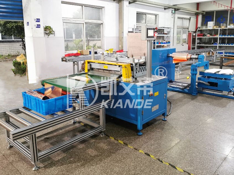
The physical process of installing blades requires strict, documented protocols. Operators must handle rotary knives with extreme care to prevent accidental micro-chipping of the carbide or tool steel edges. A microscopic chip on a slitter knife will transfer a continuous defect along the entire length of the slit coil, rendering thousands of feet of copper unusable for high-voltage applications.
Utilize specialized tooling carts and handling sleeves during all changeovers. Never allow knives to rest directly on concrete floors or steel workbenches. Proper handling protects the delicate cutting edges and ensures the tooling remains pristine between production runs. When building the tooling stack, operators must follow a precise sequence to ensure the arbor remains balanced.
Inspect the bare arbor shaft for any scoring, burrs, or residual grease that could throw off the tooling alignment.
Slide the inboard spacers onto the shaft, verifying their dimensions with a micrometer before installation.
Install the rotary knives and rubber stripper rings, ensuring the cutting edges face the correct direction for the desired shear angle.
Apply the exact specified torque to the outboard arbor nut using a calibrated torque wrench to lock the stack in place.
Torque specifications for the arbor nut are critical during installation. Over-tightening can distort the spacers, compress the rubber stripper rings unevenly, and alter the horizontal clearance. Under-tightening allows the knives to shift laterally during operation, destroying edge quality and potentially damaging the arbor keyway.
Achieving narrow coil slitting widths requires stacking rotary knives, rubber stripper rings, and steel spacers on the arbor. This stacking process can achieve widths as tight as 0.200 inches. The precision of this stack directly determines the final width of the conductor. Any error in the stack translates directly to an error in the busbar width.
Combine standard spacers with ultra-thin shims to guarantee exact strip widths. A typical setup might use a 2-inch spacer, a 0.5-inch spacer, and a 0.005-inch shim to dial in the exact dimension required. Because these spacers are machined to micrometer tolerances, the cumulative width of the stack is highly predictable, provided the components are kept in perfect condition.
Maintain absolute cleanliness during the tooling setup process. Operators must understand that a single speck of dust or a thin film of machine oil on a spacer can measure 0.0005 inches in thickness. While this seems negligible, a typical slitting setup might require stacking forty individual spacers across the arbor. If each component has a microscopic layer of debris, that error compounds across the stack, resulting in a final coil width that is out of tolerance. Technicians must wipe down every single spacer, shim, and rotary knife with a lint-free cloth immediately before sliding it onto the arbor shaft.
Setup Step | Action Item | Verification Method |
|---|---|---|
Component Inspection | Check knives and spacers for chips or burrs | Visual inspection and fingernail drag test |
Cleaning | Wipe all components with lint-free cloth and solvent | White-glove visual check before stacking |
Stack Measurement | Verify total stack width before tightening nut | Large-capacity digital caliper or micrometer |
Torque Application | Tighten arbor nut to OEM specifications | Calibrated torque wrench |
Arbor deflection involves the physical bending of the shaft under load. It poses a primary risk when slitting wide, thick copper or aluminum master coils. When the arbor bends, the horizontal clearance at the center of the shaft increases, while the clearance at the edges remains tight. This creates a variable cutting environment across a single master coil.
This deflection alters the effective cutting parameters across the width of the machine. Strands cut near the center of the arbor will exhibit heavy burrs and edge rollover due to the increased gap, while strands near the outboard supports will cut cleanly. Managing this deflection is critical for consistent quality across all slit strands.
Mitigate deflection by evaluating and utilizing specific equipment features. Outboard arbor supports provide necessary rigidity and must be locked securely in place before initiating the cut. Increased arbor diameters resist bending forces better than thinner shafts. A rigid, heavy-duty machine frame absorbs vibrations and keeps the arbors perfectly parallel under heavy cutting loads. If deflection persists, operators may need to reduce the number of cuts per pass or decrease the line speed.
Back-tension from the uncoiler and recoiling tension work together to maintain a flat strip through the slitting head. Proper tension prevents the material from wandering laterally as it enters the knives. It also ensures the slit strands rewind tightly and uniformly on the recoiler drum, preventing telescoping coils that are dangerous to handle with a forklift or overhead crane.
Set tension parameters carefully to remain below the material's yield strength. Applying too much tension will stretch the material, causing localized thinning of the conductor. This thinning alters the cross-sectional area of the busbar, which negatively impacts its current-carrying capacity and increases electrical resistance. Stretching also induces internal stresses that cause the busbar to warp during downstream punching or bending operations.
Provide operators with a clear framework for setting tension based on alloy and gauge. Aluminum requires significantly less tension than copper to prevent stretching. Proper tension control ensures dimensional stability from the master coil all the way to the final rewound slit strand. Pneumatic tension stands offer far more precise control than older mechanical friction pads.
Evaluate drive configuration options based on material properties and thickness. Pull-through slitting uses the recoiler to pull the material through free-wheeling knives. This method works well for thinner gauges. Driven slitting powers the knives directly, which is often necessary for thicker, heavier conductors to prevent the material from slipping or stalling in the slitter head.
Overall line design must adapt to specific material behaviors. Master coils are rarely perfectly flat; they typically feature a slight crown, meaning the center of the strip is thicker than the edges. When this crowned coil passes through the slitter head, the thicker center strands rewind onto the recoiler drum at a slightly larger diameter than the thinner edge strands. Because the recoiler drum rotates at a constant RPM, the larger diameter center strands pull material faster than the edge strands.
Utilize loop pits and tension stands to manage these differential rewinding speeds. A loop pit provides a physical space for the slower-rewinding edge strands to accumulate slack. Photo-eye sensors monitor the depth of these loops, ensuring the material never touches the floor. The tension stand then applies uniform back-pressure to all strands before they reach the recoiler. This synchronization is a hallmark of a high-quality coil cutting machine, preventing loose coils and internal telescoping.
Specific tension and drive setting failures map directly to common slit-in coil defects. Camber, or lateral bowing, occurs when horizontal clearance is uneven or when tension is applied asymmetrically across the width of the strip. Edge wave results from localized stretching of the material edges, often due to dull knives, improper vertical overlap, or excessive pressure from the stripper rings.
Crossbow, a longitudinal curvature across the width of the strip, typically stems from excessive recoiler tension combined with a small recoiler drum diameter. Recognizing these defects immediately allows operators to halt production and correct the underlying mechanical issue before generating massive amounts of scrap copper or aluminum.
Provide clear troubleshooting protocols for operators. They must know how to adjust tension pads, align separator discs, and position overarm separators to correct these defects in real-time. Proper use of separator tooling ensures the slit strands remain parallel and do not interweave during the recoiling process. Interwoven strands will lock together on the recoiler drum, requiring operators to manually cut and scrap the entire coil to remove it from the machine.
Defect Name | Visual Indicator | Root Cause | Corrective Action |
|---|---|---|---|
Camber | Lateral bowing of the strip | Uneven tension or uneven knife clearance | Realign tension stand pads; verify arbor parallelism |
Edge Wave | Wavy, stretched edges | Dull knives or excessive vertical overlap | Replace rotary knives; reduce vertical penetration |
Crossbow | Curvature across strip width | Excessive recoiler tension | Reduce pneumatic pressure on tension stand |
Heavy Burr | Sharp protrusion on slit edge | Excessive horizontal clearance | Recalculate and tighten horizontal knife gap |
Processing wide master coils in-house offers massive cost savings over time. It eliminates the substantial premium paid for pre-slit narrow coils sourced from external service centers. Purchasing master coils in bulk also reduces supply chain bottlenecks, lowers freight costs, and drastically shortens lead times for custom conductor dimensions.
Frame the equipment ROI around several key operational factors. Reduced raw material costs provide the most immediate financial impact. Lower inventory requirements free up warehouse space and working capital, as you no longer need to stock dozens of different pre-slit widths. Faster turnaround times for custom busduct dimensions allow manufacturers to respond rapidly to specific project requirements without waiting on external suppliers.
Calculate the payback period by comparing the monthly cost of pre-slit premiums against the amortized cost of the slitting equipment, factoring in the labor required to run the line. For high-volume facilities processing thousands of pounds of copper weekly, the ROI on a dedicated slitting line is often realized within the first two years of operation.
Traditional manual tooling setups require high operator skill and lengthy downtime. A complete arbor changeover on a manual machine can take several hours, severely limiting production throughput. This manual process is also highly susceptible to human error, leading to incorrect clearances, stacked tolerances, and scrapped material during the initial test cuts.
CNC-controlled, automated slitter heads eliminate this bottleneck. These systems use robotics or automated positioning drives to set knives and clearances in minutes. Operators simply input the material thickness, alloy type, and desired widths into the control panel, and the machine configures itself based on pre-programmed algorithms.
Evaluate the ROI of automated systems based on changeover frequency. If a facility runs multiple different coil widths per shift, automation is essential to maintain throughput. Factor in reduced labor costs, increased machine uptime, and the drastic reduction in human error when justifying the investment in automated slitting technology.
Assess the flexibility of the equipment to handle future production requirements. A machine purchased today must accommodate tomorrow's designs. This includes the ability to process wider master coils, thicker gauges, and different alloy compositions as product lines expand into higher amperage ratings.
Define the evaluation dimensions for scalability carefully. Look closely at maximum arbor capacity and weight limits for the uncoiler mandrel. Ensure the motor horsepower is sufficient to pull thicker materials without stalling or overheating. Evaluate the modularity of the tension stands and recoiler drums to ensure they can be upgraded as needed to support downstream busbar conductor processing.
Investing in a scalable machine prevents premature obsolescence. A robust, oversized frame with high torque capacity provides the necessary foundation for future upgrades, ensuring the slitting line remains a core asset for decades rather than becoming a bottleneck as production demands increase.
Audit your current slitting edge quality using a digital micrometer and optical comparator to establish a baseline for burr height and shear zone ratio.
Implement a mandatory wipe-down and inspection protocol for all spacers, shims, and rotary knives during every tooling changeover to eliminate stacked tolerance errors.
Upgrade to premium carbide rotary knives if your facility processes high volumes of copper to extend tooling life and maintain tight horizontal clearances.
Install automated tension control systems on your recoiler and tension stand to eliminate operator guesswork and prevent slit-in coil defects like camber and crossbow.
A: Horizontal knife clearance is the most critical setting. It determines the physical gap between the upper and lower rotary knives. Incorrect clearance leads directly to edge rollover, heavy burrs, and poor fracture zones, compromising the entire conductor and risking downstream insulation failure.
A: Calculate horizontal clearance based strictly on material thickness and tensile strength. For non-ferrous busbar materials like copper and aluminum, optimal clearance typically ranges from 7% to 10% of the material thickness. Harder tempers require tighter gaps to force a clean shear.
A: With precise tooling and rigid arbor configuration, a standard machine can achieve coil slitting widths as tight as 0.200 inches. This requires stacking machined spacers and ultra-thin shims to micrometer tolerances while maintaining absolute cleanliness during setup.
A: Camber, or lateral bowing, often results from uneven tension across the strip or incorrect horizontal clearance across the arbor. Fix it by adjusting the pneumatic tension pads, aligning the separator discs, and ensuring uniform knife gaps across the entire tooling stack.
A: Spacers and shims are machined to exact micrometer tolerances. Stacking standard spacers with ultra-thin shims on the arbor guarantees exact strip widths by precisely positioning the rotary knives. Any dirt or oil on these components will compound and ruin the width tolerance.
A: Pull-through slitting uses the recoiler to pull material through free-wheeling knives, which is ideal for thinner gauges. Driven slitting powers the rotary knives directly, providing the necessary mechanical force to cut thicker, heavier conductors without stalling the line.

