
Views: 0 Author: Site Editor Publish Time: 2026-10-13 Origin: Site


Positioning medium voltage (MV) cabinet frames acts as the primary bottleneck in electrical equipment manufacturing. At this stage, millimeter-level discrepancies cascade into severe downstream assembly failures. Handling heavy, unwieldy steel frames requires balancing high-throughput demands with strict safety and precision requirements. When operators misalign frames, the facility faces rejected busbar fittings, breaker insertion failures, and compromised arc-fault containment structures. These errors halt production and force extensive rework. To achieve scalable throughput and maintain strict quality control, plant managers must evaluate and implement the right mix of automated positioning systems, specialized trolleys, and integrated workstations. You must tailor these solutions to your specific facility footprint and production volume. Mastering the positioning phase ensures every subsequent component aligns perfectly, driving overall manufacturing efficiency and product reliability.
Precision dictates the success of all subsequent assembly stages; systems must guarantee sub-millimeter repeatable accuracy.
Automated Guided Vehicles (AGVs) and rail systems maximize throughput for standardized lines, while specialized material trolleys offer flexibility for custom assembly.
Integrating a dedicated auxiliary workstation at the positioning stage reduces operator fatigue, minimizes crane dependency, and accelerates cycle times.
Transitional layouts bridging manual trolleys and automated nodes allow for phased modernization without halting production.
Connecting the positioning line to MES and ERP systems ensures custom client specifications automatically dictate routing and workstation setup.
Defining the success criteria for a modern MV switchgear assembly line begins with understanding the physical challenges of the raw materials. Bare MV switchgear frames routinely exceed 1,000 kg. Maneuvering these massive steel enclosures requires specialized equipment capable of handling extreme weight while maintaining precise dimensional control. A frame that twists or warps during transit will fail strict quality assurance checks before internal components are even staged.
Positioning errors at the primary framing stage create a domino effect of downstream misalignment. When a frame sits just a fraction of a degree off-center, technicians struggle to install heavy circuit breakers smoothly. Current transformers fail to align with their designated mounting brackets. Rigid copper busbars require absolute precision to maintain proper clearance and creepage distances. Forcing a busbar into a misaligned frame introduces mechanical stress that can lead to catastrophic electrical failures in the field.
Establishing baseline safety requirements for moving heavy steel enclosures remains a top priority for facility managers. Traditional methods rely heavily on overhead crane lifts. Cranes introduce significant swing hazards and require operators to work directly under suspended loads. Modern positioning strategies focus on minimizing crane dependency. By keeping the load close to the ground and utilizing controlled horizontal movement, facilities drastically reduce pinch-point hazards and protect assembly technicians from crush injuries.
Advanced tracking and traceability elevate the positioning process from a purely mechanical task to a data-driven operation. Implementing RFID tags or barcode scanning at the positioning stage creates a searchable, real-time digital twin of the cabinet. As the frame locks into its initial station, the manufacturing execution system (MES) logs its exact location, orientation, and assigned work order. This digital handshake ensures operators receive the correct schematics and components for that specific custom build.
Moving a bare frame without its internal bracing panels exposes the structure to torsional stress. If the conveyance platform lacks proper leveling jacks, the uneven weight distribution can permanently warp the steel uprights. Plant engineers must specify transport platforms that support the frame at its engineered load-bearing points. We often see facilities damage frames simply by lifting them from the wrong corner during the initial staging phase. Using custom-machined base plates on the transport mechanism prevents this structural deflection.
Selecting the right conveyance mechanism determines the overall rhythm of the switchgear production line. Facilities must weigh throughput requirements against spatial constraints and product variability.
Floor-mounted or flush-mounted rail systems move cabinets between assembly nodes using indexed stopping points. These systems utilize heavy-duty steel tracks embedded directly into the factory floor. They guide motorized or manually pushed platforms along a fixed linear path. Once a frame reaches a designated workstation, mechanical locking pins deploy to secure the platform. This ensures zero lateral movement during component insertion.
High-volume, low-mix production environments benefit most from rail-guided systems. When a facility manufactures standardized switchgear units requiring continuous flow and rigid takt times, rails provide unmatched reliability. The fixed path eliminates navigation errors and forces a disciplined, linear assembly sequence. They offer extreme durability, high weight capacity, and minimal maintenance requirements over decades of continuous operation. Altering the factory layout requires significant infrastructure demolition and reconstruction.
AGVs utilize magnetic tape, laser guidance, or SLAM (Simultaneous Localization and Mapping) to navigate frames through the assembly sequence. Instead of following physical tracks, these robotic platforms map the factory floor and transport switchgear frames autonomously. They slide under a staged frame, lift it slightly, and carry it to the next available workstation. They adjust their routes dynamically to avoid obstacles or bypass offline stations.
Modern, scalable facilities prioritizing layout flexibility and Industry 4.0 data integration lean heavily toward AGV implementation. These systems excel in environments where product flow frequently changes based on custom orders. AGVs offer dynamic routing capabilities and direct integration with manufacturing execution systems. If a specific testing bay is occupied, the MES can redirect the AGV to an alternate bay instantly. The primary constraint involves the strict requirement for pristine, perfectly level floor conditions to ensure accurate laser navigation and prevent wheel slippage.
Purpose-built, heavy-duty wheeled platforms equipped with locking casters, leveling jacks, and custom jigs secure the cabinet base during transit. A switchgear material trolley allows operators to push or tow frames between stations. Advanced models feature hydraulic lift mechanisms to adjust the working height. This ensures technicians can reach internal mounting points without excessive bending or stretching.
High-mix, low-volume production environments and custom engineering projects rely on these trolleys for maximum adaptability. When every order features unique dimensions or specialized component layouts, rigid automation often hinders progress. Trolleys allow operators to pull a frame offline for complex, time-consuming custom work without stopping the main production flow. They introduce variability in positioning accuracy and rely heavily on operator physical effort unless paired with motorized tuggers.
Many facilities utilize a hybrid approach to balance flexibility and throughput. In a transitional layout, operators use a material trolley for initial sub-assembly and staging. Once the basic frame is prepped, the operator pushes the trolley into a localized automated rail or AGV node. The trolley locks into a standardized carrier. This carrier then navigates the frame through the highly critical main busbar installation phase where precision is paramount.
Growing facilities that need to scale production capacity incrementally utilize this method effectively. It allows operators to adapt to new technologies gradually. The hybrid model maintains the flexibility of manual staging while introducing automated precision exactly where the assembly tolerances are tightest. Success depends on careful management of the hand-off points between manual zones and automated zones. You must ensure the locking mechanisms engage flawlessly every time.
Positioning System | Navigation Method | Best Application | Primary Advantage |
|---|---|---|---|
Rail-Guided Transfer | Fixed floor tracks | High-volume, standardized | Extreme durability and weight capacity |
AGV Conveyance | SLAM / Laser guidance | Dynamic, smart factories | Route flexibility and MES integration |
Material Trolley | Manual / Motorized tugger | High-mix, custom engineering | Maximum adaptability and offline routing |
Transitional Hybrid | Trolley-to-Rail locking | Scaling facilities | Balances manual prep with automated precision |
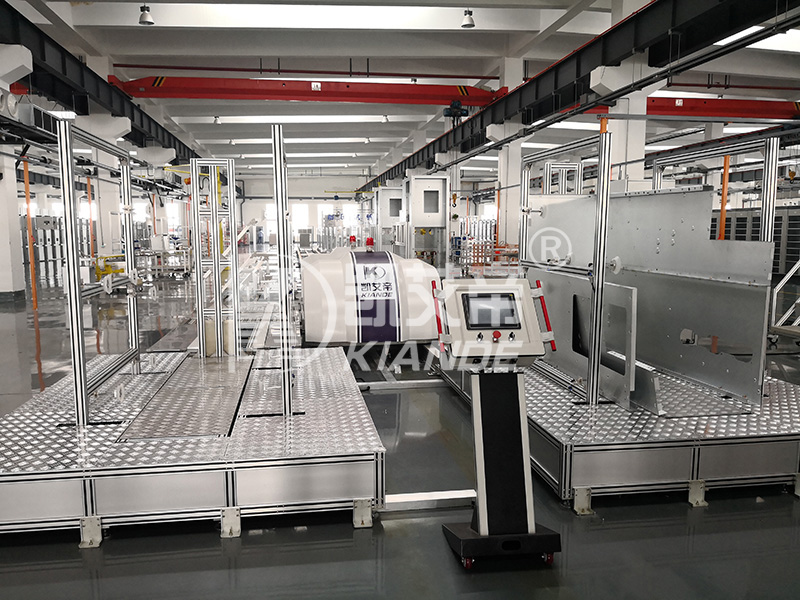
Achieving sub-millimeter accuracy requires a strict, repeatable process when locking a frame into an assembly node. Operators cannot rely on visual estimates when positioning enclosures that will house high-voltage components. The following procedure outlines the standard alignment sequence used in high-precision facilities:
Initial Staging: The operator or AGV brings the frame within 50 millimeters of the target node. Proximity sensors confirm the frame is in the correct general zone.
Rough Alignment: Guide rails or floor-mounted V-blocks catch the wheels or base plates of the conveyance platform, funneling the frame toward the center axis of the workstation.
Primary Locking: Pneumatic or hydraulic locking pins extend from the floor or the rail system, engaging with reinforced receiver holes on the transport carrier. This eliminates all lateral and longitudinal movement.
Leveling and Squaring: Automated leveling jacks deploy to lift the frame slightly off its transit wheels. This transfers the weight to solid, calibrated steel supports. Laser alignment tools verify the frame is perfectly square to the workstation tooling.
Digital Verification: The MES reads the frame's RFID tag, confirming the correct unit is in position. The system then unlocks the localized tooling and displays the specific work instructions for that node.
Secondary Clamping: For operations involving heavy torque, such as main busbar bolting, secondary overhead or side clamps engage the upper sections of the frame to prevent any micro-deflection during assembly.
Skipping any of these steps compromises the integrity of the build. If a technician attempts to install a heavy vacuum circuit breaker without engaging the secondary clamps, the frame can shift. This shift throws off the alignment of the primary disconnect contacts, leading to immediate failure during routine factory acceptance testing.
The positioning phase extends beyond simply moving the frame; it involves preparing the immediate environment for efficient assembly. A switchgear auxiliary workstation supports the main line by staging side panels, internal partitions, and mounting hardware exactly where the frame locks into place. By organizing materials adjacent to the positioning node, operators eliminate wasted movement and maintain focus on precision installation.
Evaluating workstations requires a close look at tooling and ergonomic access. The best setups feature pneumatic tool balancers that suspend heavy torque wrenches at chest height. This reduces operator fatigue. Hydraulic lift tables allow technicians to adjust the height of heavy sub-assemblies before sliding them into the main frame. Localized, high-lumen LED lighting integrated directly into the workstation ensures shadow-free visibility deep inside the dark steel enclosure. This prevents cross-threading of critical fasteners.
Decoupling sub-assembly from the main line significantly reduces overall cycle time. While the primary frame moves into position, operators at the auxiliary station prep internal components. They pre-assemble low-voltage control wire harnesses, mount terminal blocks to DIN rails, and prepare the vacuum circuit breaker chassis. When the main frame finally arrives and locks into the node, the pre-assembled modules are ready for immediate insertion. This turns a lengthy build process into a rapid integration task.
Equipping the workstation with digital work instructions transforms the assembly process. Human-Machine Interface (HMI) screens mounted on articulating arms pull real-time assembly schematics from the central server. As the frame's RFID tag registers at the station, the screen automatically updates to display the exact 3D CAD model and torque specifications required for that specific serial number. This eliminates reliance on outdated paper blueprints and drastically reduces assembly errors on highly customized orders.
Consider the installation of current transformers (CTs) and potential transformers (PTs). These cast-resin components are incredibly heavy and fragile. An optimized auxiliary workstation includes a dedicated jib crane or a zero-gravity manipulator arm specifically for handling these transformers. The operator uses the manipulator to lift the CT from its shipping crate, inspect it, and stage it on a custom jig. Once the main switchgear frame locks into the adjacent node, the operator simply swings the manipulator arm over and guides the CT onto its mounting brackets. This eliminates manual lifting and prevents accidental drops that could shatter the resin casing.
Selecting a positioning strategy requires a deep analysis of operational constraints, facility layout, and long-term production goals. Plant engineers must look beyond immediate needs and design a system capable of adapting to future product iterations.
Manufacturing engineers constantly analyze the conceptual trade-off between rapid indexing and careful alignment. Rail systems offer rapid, aggressive indexing. The platform accelerates quickly and slams into a hard mechanical stop, guaranteeing exact placement in seconds. This aggressive movement can shift loose internal components if not properly secured. Trolley-based systems require careful, manual alignment. The operator must visually align floor marks and engage locking pins manually. Calculating the acceptable cycle time for frame positioning based on overall factory takt time dictates which method is viable. If the takt time allows for a two-minute positioning window, manual trolleys suffice. If the window is thirty seconds, automated indexing is mandatory.
System adaptability remains vital for handling varying dimensions. A facility might produce compact gas-insulated switchgear (GIS) on Monday and massive air-insulated switchgear (AIS) enclosures on Tuesday. The positioning system must accommodate both without requiring hours of reconfiguration. Adjustable jigs mounted on the carriers allow operators to slide securing clamps inward or outward based on the cabinet's footprint. Fixed-dimension carriers restrict production flexibility. They force the facility to dedicate specific lines to specific product families, which limits overall operational scalability.
Implementing a new positioning system demands rigorous infrastructure assessment. Rail systems require concrete trenching, structural reinforcement, and precise leveling to prevent track binding under multi-ton loads. AGVs demand specialized floor epoxy coatings to maintain consistent friction coefficients and prevent wheel degradation. Facilities must evaluate aisle width requirements. Safe trolley maneuvering requires wide turning radii and clear lines of sight. AGVs can navigate tighter corridors provided the safety laser scanners have unobstructed views.
Custom client requests logged in an Enterprise Resource Planning (ERP) system must translate into specific routing instructions. When a client orders a switchgear lineup with non-standard relay configurations, the data triggers a specialized work order. The positioning system reads this data and automatically diverts the highly customized frame to a specialized auxiliary workstation equipped for complex wiring. This bypasses the standard high-speed assembly nodes entirely.
Furthermore, the positioning system acts as a primary data collection point for quality assurance. Every time a frame enters or leaves a node, the system timestamps the event. Plant managers use this data to identify bottlenecks. If frames consistently spend forty minutes at the busbar installation node but only twenty minutes at the breaker insertion node, engineering teams know exactly where to focus their process improvement efforts. This level of granular tracking is impossible with purely manual, un-networked positioning methods.
Transitioning to advanced positioning systems introduces specific operational risks. Identifying these vulnerabilities early allows engineering teams to implement reliable countermeasures before production halts.
Uneven factory floors pose a severe risk to both AGV navigation and rail integrity. A dip of just a few millimeters can cause an AGV's safety scanners to misread the environment, triggering an emergency stop. Uneven rails cause carrier binding, requiring heavy machinery to dislodge the jammed platform. Mitigation requires comprehensive floor topography audits using laser leveling tools. Facilities must perform localized concrete grinding or apply self-leveling epoxy prior to installing any automated conveyance system.
Data and network bottlenecks threaten the reliability of smart conveyance. Automated systems halt immediately if they experience network latency, API communication errors, or server timeouts between the fleet manager and the vehicles. A dropped Wi-Fi signal leaves a multi-ton frame stranded in a transit aisle. Deploying powerful local edge computing ensures the system processes navigation data locally rather than relying on a distant cloud server. Installing dedicated industrial 5G or high-density Wi-Fi networks isolates the AGV traffic from general facility bandwidth. Every automated carrier must feature a fail-safe manual override pendant, allowing operators to drive the unit manually during a network outage.
Worker adoption and training present significant human-factor challenges. Operators often resist new automated systems, viewing them as overly complex or a threat to their established routines. Improper use of manual locking mechanisms on hybrid systems leads to severe misalignment during busbar insertion. Mitigation strategies focus on phased rollouts. Management must provide hands-on ergonomic training, demonstrating how the new systems reduce physical strain. Clear standard operating procedures (SOPs), reinforced by visual aids at every workstation, ensure operators engage locking pins and safety interlocks correctly every time.
Maintenance downtime represents the most critical threat to throughput. A single AGV failure or a jammed rail segment halts the entire line, creating a massive bottleneck. Implementing predictive maintenance schedules prevents unexpected breakdowns. Sensors monitor wheel vibration and motor current draw, alerting technicians to bearing wear before it causes a failure. Facilities must keep redundant material trolleys on standby to bypass disabled automated nodes. Stocking critical spare parts, including drive motors, locking pins, and safety scanners, ensures maintenance teams can restore functionality within minutes rather than days.
Safety interlock failures also present a major risk during the positioning phase. If a frame is not fully locked into the node, but the system registers it as secure, operators might begin heavy torque operations. This can cause the frame to slide, potentially crushing hands or damaging components. To mitigate this, facilities must install redundant verification sensors. A primary mechanical limit switch confirms the locking pin is extended, while a secondary optical sensor verifies the frame's base plate is in the exact correct position. Both sensors must agree before the MES unlocks the workstation tooling.
To optimize your frame positioning process and eliminate downstream assembly errors, execute the following steps:
Audit your current factory floor topography using laser leveling tools to determine if the surface can support AGVs or rail systems without extensive concrete rework.
Deploy a single pilot positioning station with automated locking mechanisms to test alignment tolerances before committing to a full assembly line overhaul.
Integrate your material trolleys with your MES using RFID tags to establish baseline cycle times and identify specific bottlenecks in your current routing.
Upgrade your auxiliary workstations with pneumatic tool balancers and localized HMI screens to reduce operator fatigue and eliminate reliance on paper schematics.
A: Typical load requirements range from 1,000 kg to 3,000 kg. The exact capacity depends on the switchgear type, with air-insulated switchgear (AIS) generally requiring higher capacities due to larger steel enclosures compared to compact gas-insulated switchgear (GIS).
A: Frame squareness and rigidity directly impact the strict tolerances required for copper busbar alignment. If the frame is positioned unevenly, the mounting points skew. This forces technicians to bend or stress the rigid copper, which can lead to mechanical failure or arc faults.
A: While AGVs efficiently handle horizontal transit between workstations, cranes or localized hoists are still required for the initial loading of the bare frame onto the carrier. They are also necessary for inserting exceptionally heavy internal components like large vacuum circuit breakers.
A: It serves as a dedicated area to stage tools, hardware, and sub-assemblies adjacent to the main frame. This setup minimizes operator movement, reduces fatigue, and significantly speeds up the assembly process by keeping all necessary materials within arm's reach.
A: Positional accuracy on manual lines is maintained through the use of floor-mounted indexing pins, heavy-duty locking casters, and custom jigs. Operators also use laser alignment tools to verify the frame is perfectly square before beginning component installation.
A: Automated systems, especially AGVs, require exceptionally flat floors with specific friction coefficients to prevent wheel slip. The surface must be free of deep cracks, uneven expansion joints, and debris that could interfere with laser navigation scanners or rail mechanisms.
A: Customer order data from ERP systems dictates the automated routing of frames. When a custom order is processed, the software instructs the conveyance system to route the frame to specific auxiliary workstations equipped for those unique component installations.

